Publication Cover
Structure and Infrastructure Engineering
Maintenance, Management, Life-Cycle Design and Performance
Volume 13, 2017 - Issue 5
3,532
Views
11
CrossRef citations to date
0
Altmetric
Articles

Relating the structural strength of concrete sewer pipes and material properties retrieved from core samples

, , &
Pages 637-651 | Received 13 Aug 2015, Accepted 26 Mar 2016, Published online: 05 Jun 2016

Figures & data

Table 1. Characteristics of studied sewer pipes.

Figure 1. Schematic diagram of the adopted experiment principle (left) and actual experimental set-up (right).
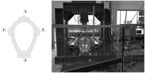
Figure 1. Schematic diagram of the adopted experiment principle (left) and actual experimental set-up (right).

Figure 2. Test set-up used for four-point loading flexural tests.

Figure 2. Test set-up used for four-point loading flexural tests.

Figure 3. Successive stages in the test of a sewer pipe (P02) from Municipality of The Hague during the experiment.
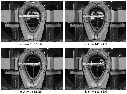
Figure 3. Successive stages in the test of a sewer pipe (P02) from Municipality of The Hague during the experiment.

Figure 4. Force-displacement response for; (a,b) the 61-year-old sewer pipes - P02, P06; (c,d) the 89-year-old sewer pipes - P08, P10; (e) the new sewer pipe - P01. Legend: Fv – vertical force; Fh – horizontal force; δfv – front vertical displacement; δfh – front horizontal displacement; δbv – back vertical displacement; δbh – back horizontal displacement.
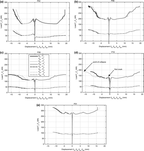
Figure 4. Force-displacement response for; (a,b) the 61-year-old sewer pipes - P02, P06; (c,d) the 89-year-old sewer pipes - P08, P10; (e) the new sewer pipe - P01. Legend: Fv – vertical force; Fh – horizontal force; δfv – front vertical displacement; δfh – front horizontal displacement; δbv – back vertical displacement; δbh – back horizontal displacement.

Figure 5. Boxplot for the carbonation depths at the inside for pipes P02, P06, P08 and P10; discriminating between crown, lateral and invert positions. On each box, the central mark is the median, the edges of the box are the 25th and 75th percentiles, the whiskers extend to the most extreme data points not considered outliers (approximately ± 2.7σ), and outliers are plotted individually.
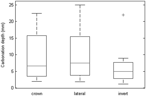
Figure 5. Boxplot for the carbonation depths at the inside for pipes P02, P06, P08 and P10; discriminating between crown, lateral and invert positions. On each box, the central mark is the median, the edges of the box are the 25th and 75th percentiles, the whiskers extend to the most extreme data points not considered outliers (approximately ± 2.7σ), and outliers are plotted individually.
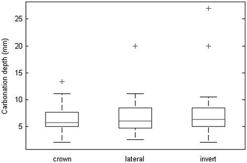
Figure 6. Boxplot for the carbonation depths at the outside for pipes P02, P06, P08 and P10; discriminating between crown, lateral and invert regions. On each box, the central mark is the median, the edges of the box are the 25th and 75th percentiles, the whiskers extend to the most extreme data points not considered outliers (approximately ± 2.7σ), and outliers are plotted individually.

Figure 6. Boxplot for the carbonation depths at the outside for pipes P02, P06, P08 and P10; discriminating between crown, lateral and invert regions. On each box, the central mark is the median, the edges of the box are the 25th and 75th percentiles, the whiskers extend to the most extreme data points not considered outliers (approximately ± 2.7σ), and outliers are plotted individually.

Figure 7. The four-pint flexural test force-deformation response for; (a) the new sewer pipe – P01; (b) the 60-year-old sewer pipe – P02; (c) the 90-year-old sewer pipe – P08.
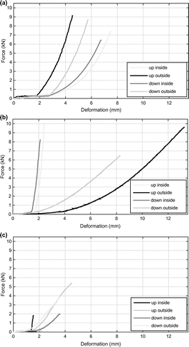
Figure 7. The four-pint flexural test force-deformation response for; (a) the new sewer pipe – P01; (b) the 60-year-old sewer pipe – P02; (c) the 90-year-old sewer pipe – P08.

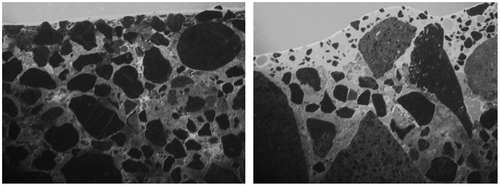
Figure 8. Examples of the studied thin section under the fluorescence light (P02 and P06).

Figure 8. Examples of the studied thin section under the fluorescence light (P02 and P06).

Figure 9. Examples of the studied thin sections under the polarised light with the highlighted ettringite (P06 and P02).
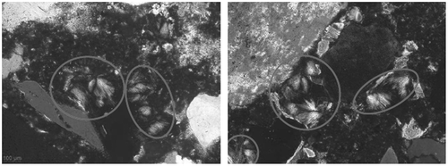
Figure 9. Examples of the studied thin sections under the polarised light with the highlighted ettringite (P06 and P02).

Figure 10. Relation between force at the first crack and carbonation depth at the inner wall of the pipes.
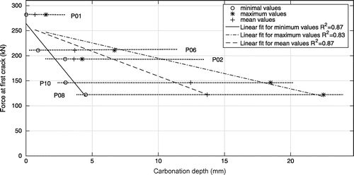
Figure 10. Relation between force at the first crack and carbonation depth at the inner wall of the pipes.

Figure 11. Relation between force at the first crack and the carbonation depth at the inside and outside wall of the pipes.
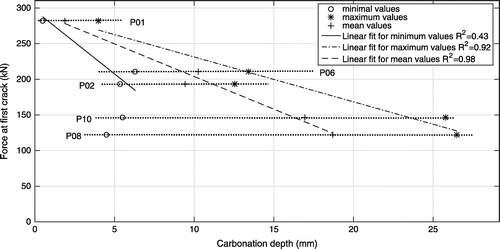
Figure 11. Relation between force at the first crack and the carbonation depth at the inside and outside wall of the pipes.

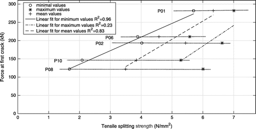
Figure 12. Relation between force at the first crack and the tensile splitting strength.

Figure 12. Relation between force at the first crack and the tensile splitting strength.

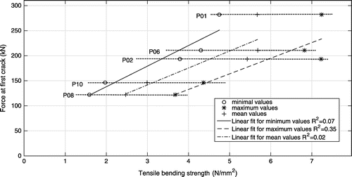
Figure 13. Relation between force at the first crack and the tensile bending strength.

Figure 13. Relation between force at the first crack and the tensile bending strength.

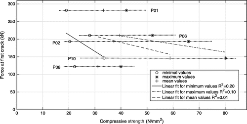
Figure 14. Relation between force at the first crack and the compressive strength.

Figure 14. Relation between force at the first crack and the compressive strength.

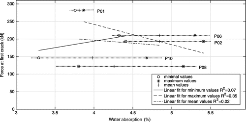
Figure 15. Relation between force at the first crack and the water absorption.

Figure 15. Relation between force at the first crack and the water absorption.

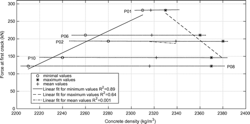
Figure 16. Relation between force at the first crack and the density of the concrete.

Figure 16. Relation between force at the first crack and the density of the concrete.

Figure 17. Relation between thickness of the remaining healthy material and force at the first crack.
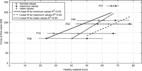
Figure 17. Relation between thickness of the remaining healthy material and force at the first crack.
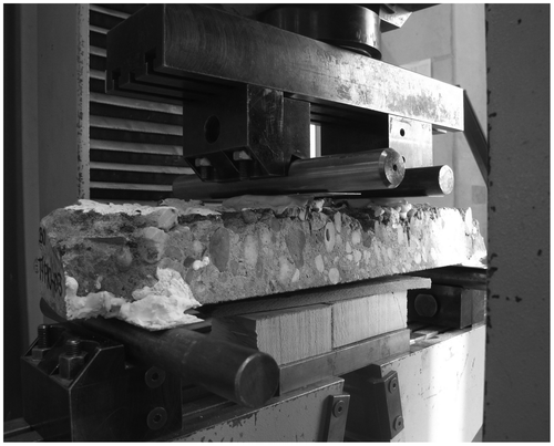
Table 2. Relation between carbonation depth and bending tensile strength.

Table 3. Calculated sample size required for 95% reliability.

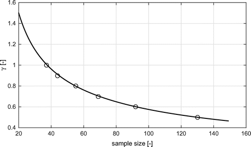
Figure 18. Relation between relative confidence interval and sample size.

Figure 18. Relation between relative confidence interval and sample size.