2,969
Views
8
CrossRef citations to date
0
Altmetric
Articles

A full-color anaglyph three-dimensional display system using active color filter glasses

, , , , , & show all
Pages 37-41 | Received 16 Oct 2010, Accepted 23 Nov 2010, Published online: 16 Mar 2011

Figures & data

Figure 1. Basic concept of the full-color anaglyph system using an active color filter.

Figure 1. Basic concept of the full-color anaglyph system using an active color filter.

Figure 2. The mechanism of how the observer sees full-color 3D images with the synchronized active color filter and the display panel.
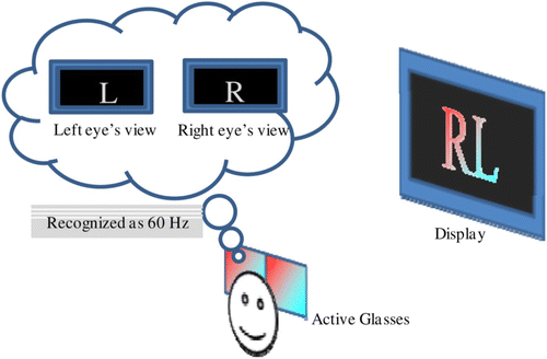
Figure 2. The mechanism of how the observer sees full-color 3D images with the synchronized active color filter and the display panel.

Figure 3. Making an active color filter from a liquid crystal display monitor.

Figure 3. Making an active color filter from a liquid crystal display monitor.

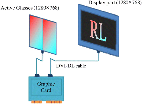
Figure 4. Full-color anaglyph system schematic overview.

Figure 4. Full-color anaglyph system schematic overview.

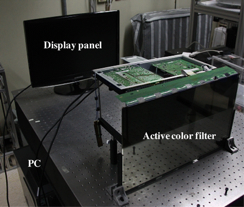
Figure 5. Full-color anaglyph system experiment setup.

Figure 5. Full-color anaglyph system experiment setup.

Figure 6. The original images that were used in the image separation experiment: (a) the left-eye image; and (b) the right-eye image.
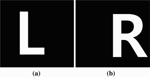
Figure 6. The original images that were used in the image separation experiment: (a) the left-eye image; and (b) the right-eye image.

Figure 7. The rendered images in the image separation experiment: (a) the first-status image and (b) the second-status image.
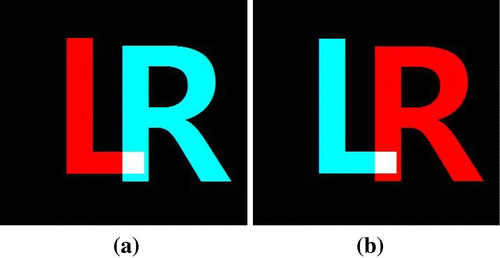
Figure 7. The rendered images in the image separation experiment: (a) the first-status image and (b) the second-status image.

Figure 8. The original images that were used in the experiment with stereoscopic images: (a) the left-eye image and (b) the right-eye image.
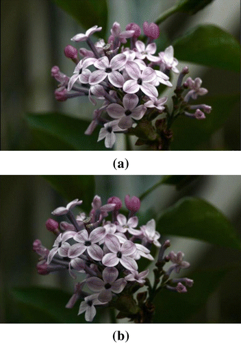
Figure 8. The original images that were used in the experiment with stereoscopic images: (a) the left-eye image and (b) the right-eye image.

Figure 9. The rendered images in the experiment with stereoscopic images: (a) the first-status image and (b) the second-status image.
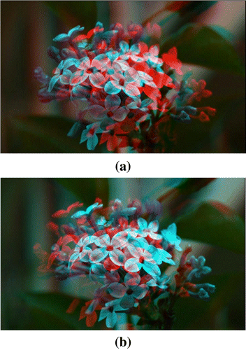
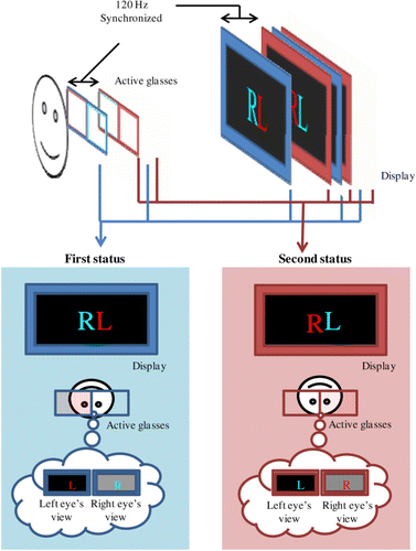
Figure 9. The rendered images in the experiment with stereoscopic images: (a) the first-status image and (b) the second-status image.
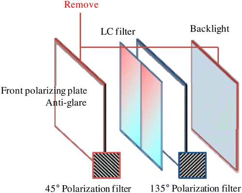
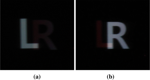
Figure 10. The results of the image separation experiment: (a) the left-eye view and (b) the right-eye view.

Figure 10. The results of the image separation experiment: (a) the left-eye view and (b) the right-eye view.

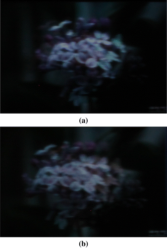
Figure 11. The results of the experiment with stereoscopic images: (a) the left-eye view and (b) the right-eye view.

Figure 11. The results of the experiment with stereoscopic images: (a) the left-eye view and (b) the right-eye view.

Reprints and Corporate Permissions

Please note: Selecting permissions does not provide access to the full text of the article, please see our help page How do I view content?

To request a reprint or corporate permissions for this article, please click on the relevant link below:

Academic Permissions

Please note: Selecting permissions does not provide access to the full text of the article, please see our help page How do I view content?

Obtain permissions instantly via Rightslink by clicking on the button below:

If you are unable to obtain permissions via Rightslink, please complete and submit this Permissions form. For more information, please visit our Permissions help page.