743
Views
5
CrossRef citations to date
0
Altmetric
Articles

Effect of the active-layer thickness on the short-circuit current analyzed using the generalized transfer matrix method

, , , , &
Pages 7-11 | Received 22 Nov 2011, Accepted 25 Nov 2012, Published online: 21 Dec 2012

Figures & data

Figure 1. (a) Schematic diagram of the OSC structure with mixed incoherent and coherent multilayers. (b) The corresponding device structure of the OSC.
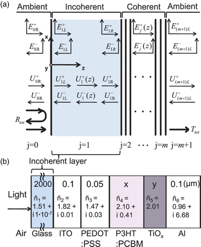
Figure 1. (a) Schematic diagram of the OSC structure with mixed incoherent and coherent multilayers. (b) The corresponding device structure of the OSC.

Figure 2. (a) The relationship between the Poynting vector (power density flow) and the power dissipation in the active layer. (b) Spectral irradiance from the sun measured at the top of the atmosphere (AM0 ASTM E490, red line) and at the ground incident at 48.2° (AM1.5 ASTM G-173, blue line) Citation14. The AM 1.5 ASTM G-175 used in this simulation has a 1000 W/m2 irradiance.
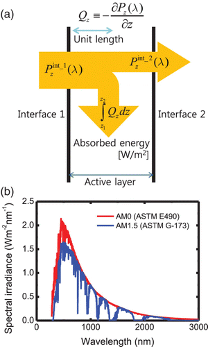
Figure 2. (a) The relationship between the Poynting vector (power density flow) and the power dissipation in the active layer. (b) Spectral irradiance from the sun measured at the top of the atmosphere (AM0 ASTM E490, red line) and at the ground incident at 48.2° (AM1.5 ASTM G-173, blue line) Citation14. The AM 1.5 ASTM G-175 used in this simulation has a 1000 W/m2 irradiance.

Figure 3. (a) Refractive indices and (b) absorption coefficients used in this simulation. The optical constants of ITO, PEDOT:PSS, P3HT:PCBM, and Al were taken from Citation15, that for TiO x was taken from Citation16, and that for glass was taken from Citation17.
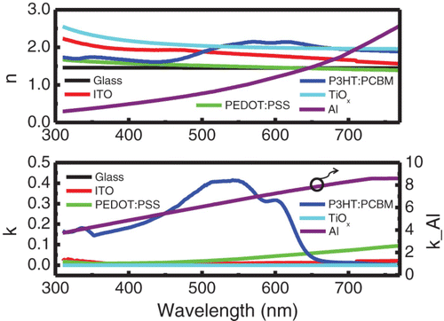
Figure 3. (a) Refractive indices and (b) absorption coefficients used in this simulation. The optical constants of ITO, PEDOT:PSS, P3HT:PCBM, and Al were taken from Citation15, that for TiO x was taken from Citation16, and that for glass was taken from Citation17.

Figure 4. Calculation of the normalized Poynting vector (power density flow) at the optical-spacer thicknesses of 5, 10, 15, and 20 nm. The wavelength of the incident light was 550 nm.
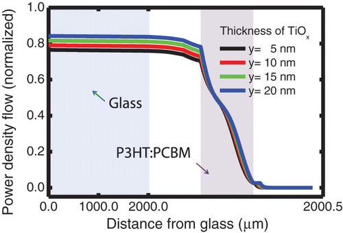
Figure 4. Calculation of the normalized Poynting vector (power density flow) at the optical-spacer thicknesses of 5, 10, 15, and 20 nm. The wavelength of the incident light was 550 nm.

Figure 5. Two-dimensional contour plot for the time-averaged Poynting vector (power density flow) as a function of wavelength and position. The optical-spacer thickness was 20 nm, and the wavelength varied from 310 to 770 nm.
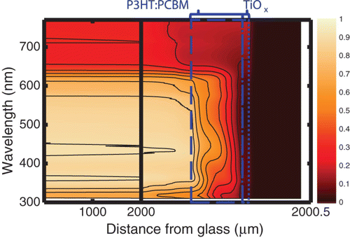
Figure 5. Two-dimensional contour plot for the time-averaged Poynting vector (power density flow) as a function of wavelength and position. The optical-spacer thickness was 20 nm, and the wavelength varied from 310 to 770 nm.

Figure 6. Calculated maximum short-circuit current as a function of the active-layer thickness for the optical-spacer layer thicknesses of 5, 10, 15, and 20 nm. The wavelength interval for the calculation was between 310 and 770 nm.
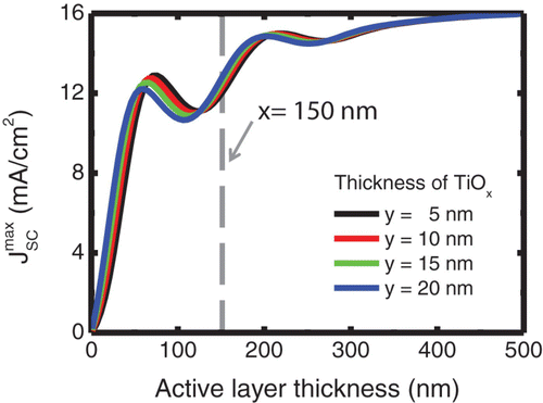
Figure 6. Calculated maximum short-circuit current as a function of the active-layer thickness for the optical-spacer layer thicknesses of 5, 10, 15, and 20 nm. The wavelength interval for the calculation was between 310 and 770 nm.

Reprints and Corporate Permissions

Please note: Selecting permissions does not provide access to the full text of the article, please see our help page How do I view content?

To request a reprint or corporate permissions for this article, please click on the relevant link below:

Academic Permissions

Please note: Selecting permissions does not provide access to the full text of the article, please see our help page How do I view content?

Obtain permissions instantly via Rightslink by clicking on the button below:

If you are unable to obtain permissions via Rightslink, please complete and submit this Permissions form. For more information, please visit our Permissions help page.