
Figures & data
Figure 1. The emission process of the conventional TTF device and TTF-AM device.
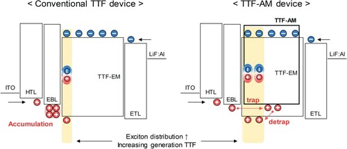
Figure 2. (a) Energy level diagram of devices and chemical structure of materials, (b) Current density-voltage-luminance (J-V-L), (c) External quantum efficiency (EQE)-current density, and (d) EL spectra at 1,000 cd/m2 of the TTF devices.
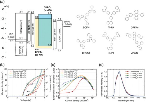
Figure 3. The transient EL measurement from low to high current density range according to the doping concentration of the TTF-AM (10, 20, and 30 wt%) of the conventional TTF and TTF-AM device: (a) 10, (b) 70, (c) 150 current density and EL intensity-1/2-time (inset), and (d) EQE-current density (up) and TTF ratio-current density (down).
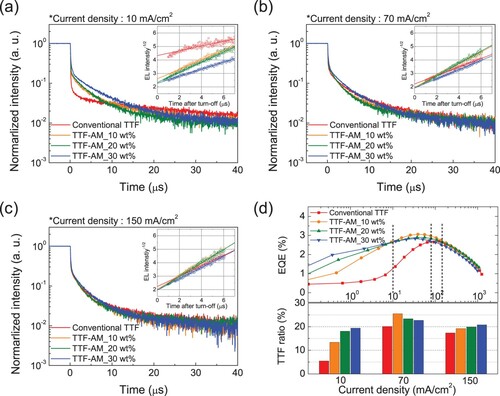
Figure 4. The transient EL of the conventional TTF and TTF-AM doped (30 wt% doping) devices at voltage pulses of (a) 1, (b) 10, (c) 50, and (d) 100 µs under a current density of 150 mA/cm2.
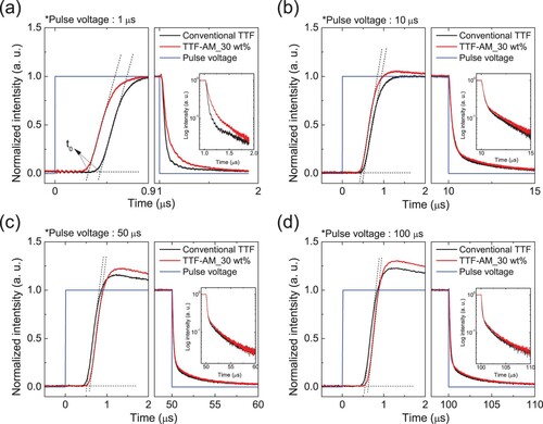
Figure 5. The impedance data of conventional TTF and TTF-AM 30 wt% devices: (a) capacitance-voltage at AC frequency of 50 Hz, 3-D plot of capacitance-frequency-voltage of (b) conventional TTF, and (c) TTF-AM 30 wt% device (light-emitting devices in [a] and hole-only device in [b, c]).
![Figure 5. The impedance data of conventional TTF and TTF-AM 30 wt% devices: (a) capacitance-voltage at AC frequency of 50 Hz, 3-D plot of capacitance-frequency-voltage of (b) conventional TTF, and (c) TTF-AM 30 wt% device (light-emitting devices in [a] and hole-only device in [b, c]).](/cms/asset/47d441e5-204f-478c-b994-8c01776b51fb/tjid_a_2089750_f0005_oc.jpg)
Table 1. Summarized device performances of the TTF devices with 10, 20, and 30 wt% TTF-AM.