837
Views
2
CrossRef citations to date
0
Altmetric
Original Articles

Background error covariances for a BlendVar assimilation system

&
Article: 1355718 | Received 22 Dec 2016, Accepted 04 Jul 2017, Published online: 03 Aug 2017

Figures & data

Figure 1. Vertical profiles of background error standard deviations for ENSBV (red solid line) and ENS (green dashed line) for: (a) specific humidity, (b) vorticity, (c) specific humidity rescaled, (d) vorticity rescaled.
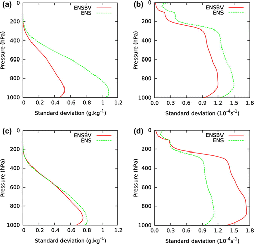
Figure 1. Vertical profiles of background error standard deviations for ENSBV (red solid line) and ENS (green dashed line) for: (a) specific humidity, (b) vorticity, (c) specific humidity rescaled, (d) vorticity rescaled.

Figure 2. Horizontal variance spectra of background errors at 850 hPa (the model level 63) for (a) specific humidity, (b) vorticity, (c) specific humidity with rescaling, (d) vorticity with rescaling. The red solid line indicates the ENSBV spectra, the green dashed line indicates the ENS spectra and the black dotted line indicates wavelength of the DF Blending cut-off truncation.
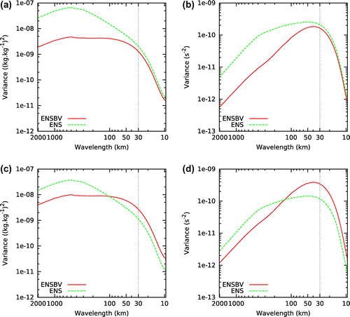
Figure 2. Horizontal variance spectra of background errors at 850 hPa (the model level 63) for (a) specific humidity, (b) vorticity, (c) specific humidity with rescaling, (d) vorticity with rescaling. The red solid line indicates the ENSBV spectra, the green dashed line indicates the ENS spectra and the black dotted line indicates wavelength of the DF Blending cut-off truncation.

Figure 3. Horizontal background errors correlation functions for temperature at 500 hPa (model level 34) for ENSBV (red solid line) and ENS (green dashed line).
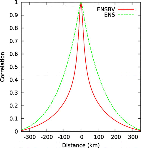
Figure 3. Horizontal background errors correlation functions for temperature at 500 hPa (model level 34) for ENSBV (red solid line) and ENS (green dashed line).

Figure 4. Vertical profiles of horizontal length scales for vorticity (vor) and specific humidity (q) for ENSBV (red lines) and ENS (green lines).
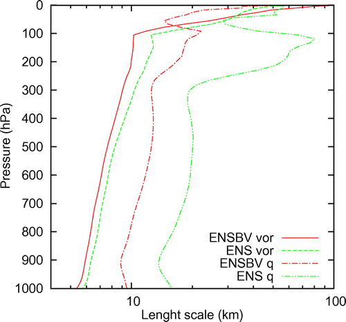
Figure 4. Vertical profiles of horizontal length scales for vorticity (vor) and specific humidity (q) for ENSBV (red lines) and ENS (green lines).

Figure 5. Vertical correlations at 500 hPa (model level 34) of temperature background errors for ENSBV (red solid line) and ENS (green dashed line).
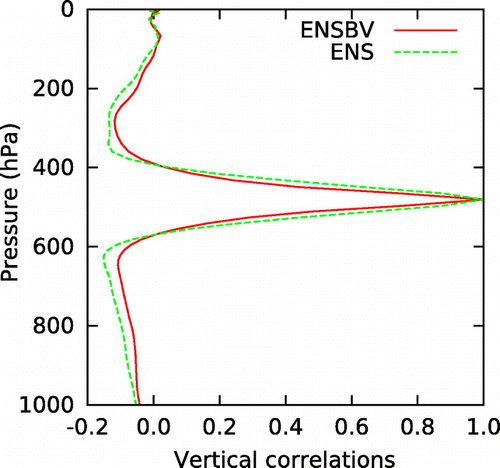
Figure 5. Vertical correlations at 500 hPa (model level 34) of temperature background errors for ENSBV (red solid line) and ENS (green dashed line).

Figure 6. Vertical profiles of percentages of error variances (spectral averages) explained by balanced geopotential for specific humidity (a), temperature (b) and divergence (c), by unbalanced divergence for specific humidity (d) and temperature (e) and unbalanced temperature for specific humidity (f). The red solid line indicates the ENSBV profiles and the green dashed line the ENS profiles.
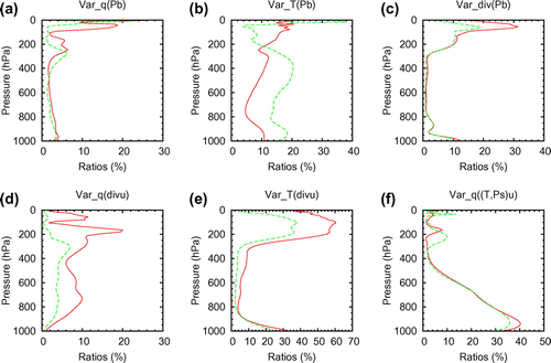
Figure 6. Vertical profiles of percentages of error variances (spectral averages) explained by balanced geopotential for specific humidity (a), temperature (b) and divergence (c), by unbalanced divergence for specific humidity (d) and temperature (e) and unbalanced temperature for specific humidity (f). The red solid line indicates the ENSBV profiles and the green dashed line the ENS profiles.

Figure 7. Temporal evolution of the surface pressure tendency root mean square averaged over the model domain and 8 forecasts as a function of the forecast range for both ensembles, ENSBV (red solid line) and ENS (green dashed line).
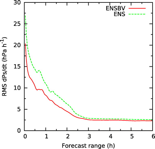
Figure 7. Temporal evolution of the surface pressure tendency root mean square averaged over the model domain and 8 forecasts as a function of the forecast range for both ensembles, ENSBV (red solid line) and ENS (green dashed line).

Figure 8. Evolution of horizontal variance spectra of background errors at 500 hPa (model level 34) for (a) vorticity of ENS, (b) vorticity of ENSBV, (c) specific humidity of ENS, (d) specific humidity of ENSBV. The estimated spectra for +6 h (red solid line), +0 h (green dashed line), +1 h (blue short dashed line), +3 h (pink dotted line), +5 h (light blue dashed dotted line) and variance spectra after application of DF Blending in each member of ENSBV (brown short dashed dotted line).
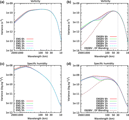
Figure 8. Evolution of horizontal variance spectra of background errors at 500 hPa (model level 34) for (a) vorticity of ENS, (b) vorticity of ENSBV, (c) specific humidity of ENS, (d) specific humidity of ENSBV. The estimated spectra for +6 h (red solid line), +0 h (green dashed line), +1 h (blue short dashed line), +3 h (pink dotted line), +5 h (light blue dashed dotted line) and variance spectra after application of DF Blending in each member of ENSBV (brown short dashed dotted line).

Figure 9. Number of observations used for verification: (a) vertical profile of number of radiosonde (red line) and aircraft (black line) temperature observations used in verification of assimilation cycles; (b) evolution of number of aircraft temperature observations by forecast range. The used observations are divided to vertical bins, where thresholds are halves of intervals between two labelled levels (e.g. level 850 hPa uses the interval 775–900 hPa).
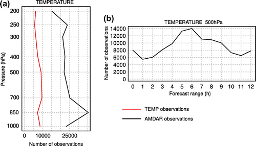
Figure 9. Number of observations used for verification: (a) vertical profile of number of radiosonde (red line) and aircraft (black line) temperature observations used in verification of assimilation cycles; (b) evolution of number of aircraft temperature observations by forecast range. The used observations are divided to vertical bins, where thresholds are halves of intervals between two labelled levels (e.g. level 850 hPa uses the interval 775–900 hPa).

Figure 10. Vertical profiles of 6-hour forecasts RMSE inside assimilation cycles verified against radiosonde observations: (a) relative humidity profiles, (b) wind speed profiles, (c) temperature profiles. The profiles are shown for BlendVar_ensbv (red line), BlendVar_ens (black line), Blending (yellow line) and 3D-Var_ens (green line). Full circles denotes a statistically significant difference (at the 95% confidence level) with respect to the scores of BlendVar_ensbv.
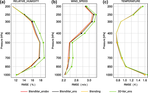
Figure 10. Vertical profiles of 6-hour forecasts RMSE inside assimilation cycles verified against radiosonde observations: (a) relative humidity profiles, (b) wind speed profiles, (c) temperature profiles. The profiles are shown for BlendVar_ensbv (red line), BlendVar_ens (black line), Blending (yellow line) and 3D-Var_ens (green line). Full circles denotes a statistically significant difference (at the 95% confidence level) with respect to the scores of BlendVar_ensbv.
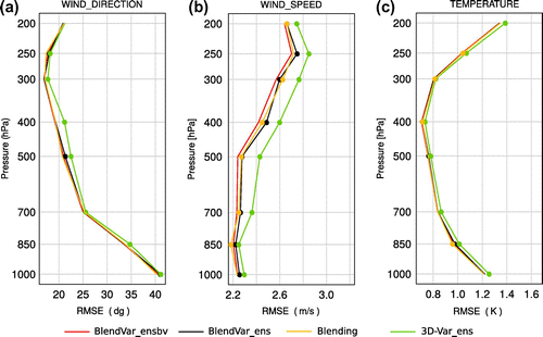
Figure 11. Vertical profiles of 6-hour forecasts RMSE inside assimilation cycles verified against aircraft observations (AMDAR): (a) wind direction profiles, (b) wind speed profiles, (c) temperature profiles. The profiles are shown for BlendVar_ensbv (red line), BlendVar_ens (black line), Blending (yellow line) and 3D-Var_ens (green line). Full circles denotes a statistically significant difference (at the 95% confidence level) with respect to the scores of BlendVar_ensbv.

Figure 11. Vertical profiles of 6-hour forecasts RMSE inside assimilation cycles verified against aircraft observations (AMDAR): (a) wind direction profiles, (b) wind speed profiles, (c) temperature profiles. The profiles are shown for BlendVar_ensbv (red line), BlendVar_ens (black line), Blending (yellow line) and 3D-Var_ens (green line). Full circles denotes a statistically significant difference (at the 95% confidence level) with respect to the scores of BlendVar_ensbv.

Figure 12. Time evolution of RMSE with forecast range for (a) temperature, (b) wind speed at 500 hPa verified against radiosondes and aircraft observations together. The scores are shown for BlendVar_ensbv (red line), BlendVar_ens (black line), Blending (yellow line) and 3D-Var_ens (green line).
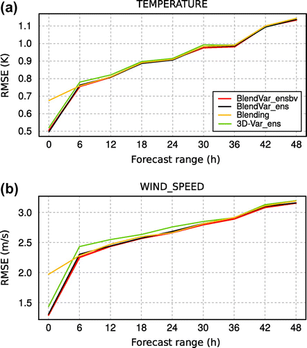
Figure 12. Time evolution of RMSE with forecast range for (a) temperature, (b) wind speed at 500 hPa verified against radiosondes and aircraft observations together. The scores are shown for BlendVar_ensbv (red line), BlendVar_ens (black line), Blending (yellow line) and 3D-Var_ens (green line).

Figure 13. Time evolution of RMSE with forecast range by hour for (a) temperature, (b) wind speed at 500 hPa verified against aircraft observations. The scores are shown for BlendVar_ensbv (red line), BlendVar_ens (black line), Blending (yellow line) and 3D-Var_ens (green line). Full circles denotes a statistically significant difference (at the 95% confidence level) with respect to the scores of BlendVar_ensbv.
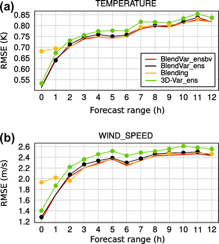
Figure 13. Time evolution of RMSE with forecast range by hour for (a) temperature, (b) wind speed at 500 hPa verified against aircraft observations. The scores are shown for BlendVar_ensbv (red line), BlendVar_ens (black line), Blending (yellow line) and 3D-Var_ens (green line). Full circles denotes a statistically significant difference (at the 95% confidence level) with respect to the scores of BlendVar_ensbv.