Figures & data
Figure 1. Schematic diagram of the OCFs system (a) and (b) Tested channel model.
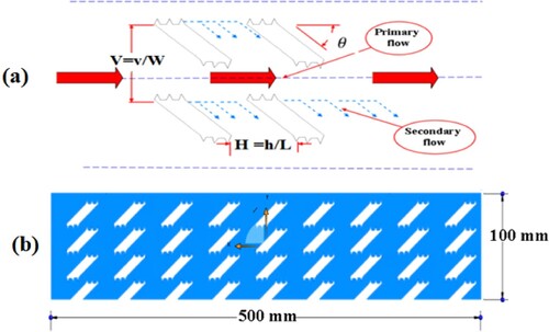
Table 1. Design parameters of OCF.
Figure 2. Grid independence test for the current study.
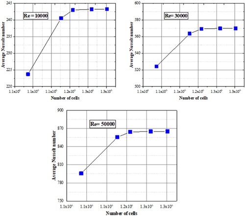
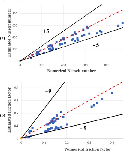
Figure 3. Generated mesh of proposed channel and validation of the current numerical result with (a) Unger et al. [Citation35], and (b) Ibrahim et al. [Citation36].
![Figure 3. Generated mesh of proposed channel and validation of the current numerical result with (a) Unger et al. [Citation35], and (b) Ibrahim et al. [Citation36].](/cms/asset/e2229b2c-dafa-4bec-9bd3-4cb0d0cda85a/tusc_a_2234705_f0003_oc.jpg)
Figure 4. Comparison between channel with an oblique fin without corrugation (right) and the other with triangular oblique-corrugated fin (left) in terms of various contours: (a) Isotherms, (b) Velocity, (c) Turbulent kinetic energy, and (d) Vortices contours, at Re = 10000.
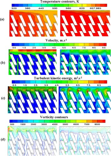
Figure 5. Isotherms and vortices contours of tested model with triangular oblique-corrugated fin under different horizontal gap ratios.
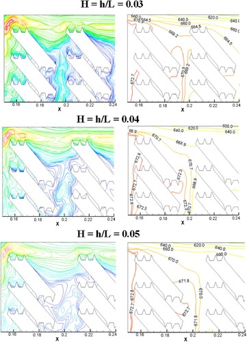
Figure 6. Impacts of various horizontal gap ratios (H) on the heat transfer characteristics of triangular oblique-corrugated fin at oblique angle 40 and vertical gap ratio 0.15: (a) Average Nu, (b) Friction factor, and (c) PEC.

Figure 7. Impacts of various horizontal gap ratios (H) on the heat transfer characteristics of triangular oblique-corrugated fin at oblique angle 40 and vertical gap ratio 0.2: (a) Average Nu, (b) Friction factor, and (c) PEC.
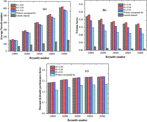
Figure 8. Impacts of various horizontal gap ratios (H) on the heat transfer characteristics of triangular oblique-corrugated fin at oblique angle 40 and vertical gap ratio 0.25: (a) Average Nu, (b) Friction factor, and (c) PEC.
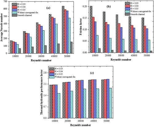
Figure 9. Isotherms and vortices contours of tested model with triangular oblique-corrugated fin under different vertical gap ratios.
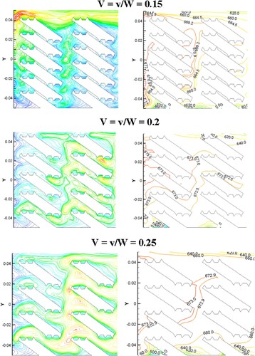
Figure 10. Impacts of various vertical gap ratios (V) on the heat transfer characteristics of triangular oblique-corrugated fin at oblique angle 40 and horizontal gap ratio 0.03: (a) Average Nu, (b) Friction factor, and (c) PEC.
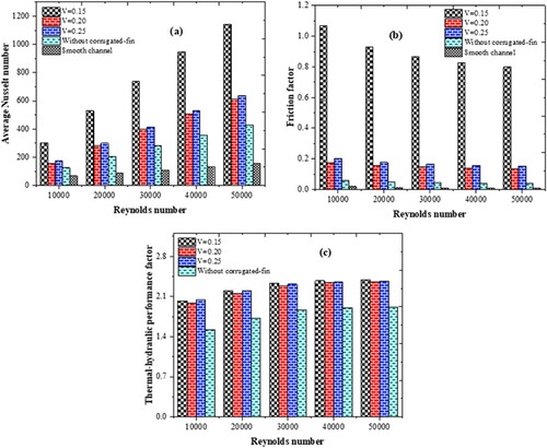
Figure 11. Impacts of various vertical gap ratios (V) on the heat transfer characteristics of triangular oblique-corrugated fin at oblique angle 40 and horizontal gap ratio 0.04: (a) Average Nu, (b) Friction factor, and (c) PEC.
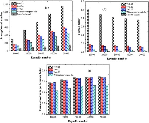
Figure 12. Impacts of various vertical gap ratios (V) on the heat transfer characteristics of triangular oblique-corrugated fin at oblique angle 40 and horizontal gap ratio 0.05: (a) Average Nu, (b) Friction factor, and (c) PEC.
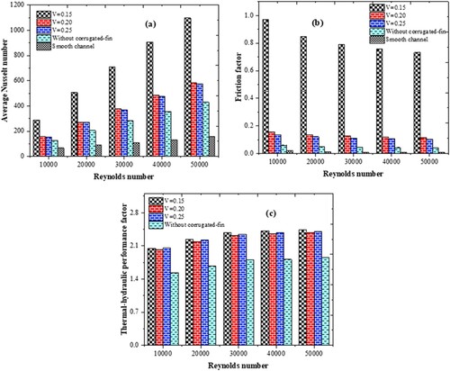
Figure 13. Comparison of various vertical and horizontal gap ratios on the heat transfer characteristics, (a) Average Nu, (b) Friction factor, and (c) PEC.
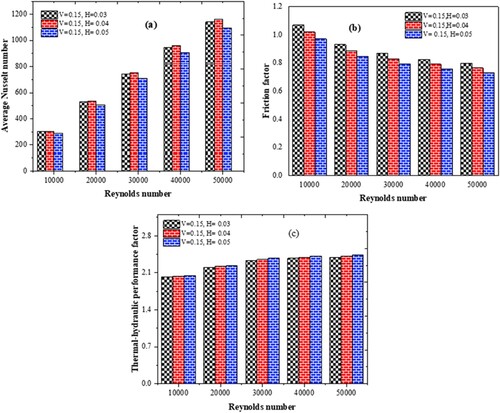
Figure 14. Impacts of oblique-corrugated fin angles on the heat transfer characteristics, (a) Average Nu, (b) Friction factor, and (c) PEC.
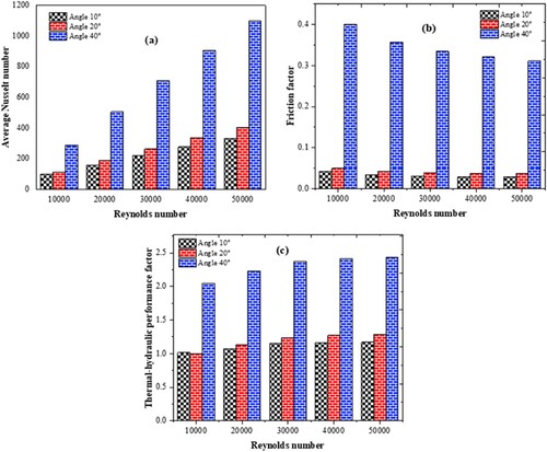
Figure 15. Recommended correlations of OFC in terms of: (a) Nusselt number, and (b) Friction factor.