Figures & data
Figure 1. Schematic of a tunnel supported by end-anchored bolts and lining with a void behind the lining.
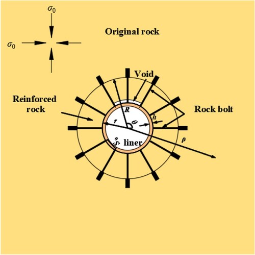
Figure 2. Rock under the actions of end-anchored bolts and lining in an infinite medium. Fig. (a) is equivalent to the superposition of Figs (b) and (c).
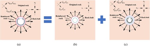
Figure 3. Lining stress when the rock is reinforced by end-anchored bolts.
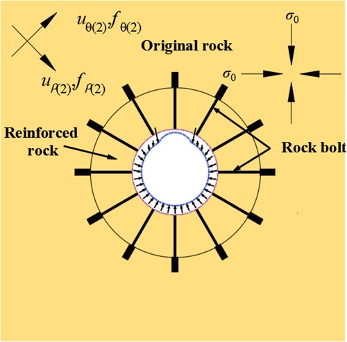
Figure 4. Schematic of the interaction between the bolt and the rock in the reinforced area.
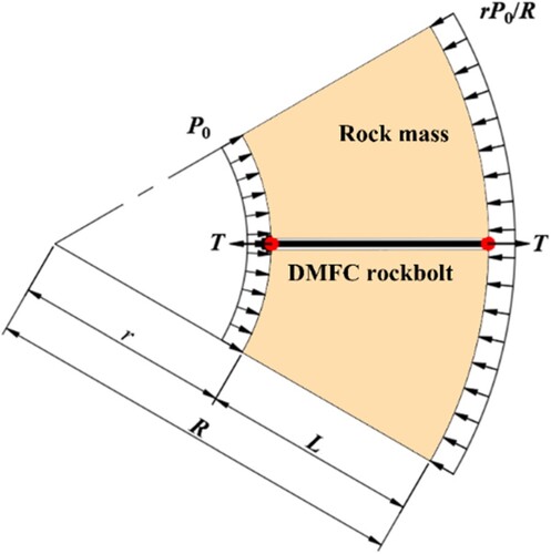
Table 1. Material properties.
Table 2. Numerical solutions for lining and tunnel reinforced by end-anchored bolts.
Figure 5. Evolution of tunnel stress and displacement in the radial direction.
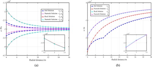
Figure 6. Evolution of the reaction force on the lining from the rock reinforced by end-anchored bolts and lining.
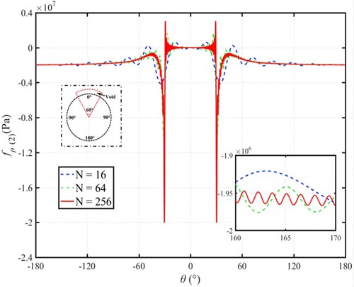
Figure 7. Evolution of the lining displacement in tunnel reinforced by end-anchored bolts and lining.
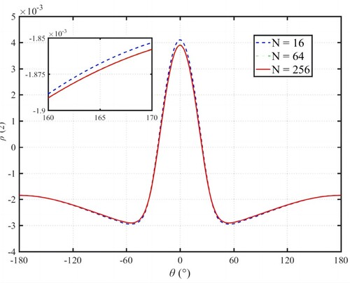
Figure 8. Evolution of the axial force and bending moment for tunnel reinforced by end-anchored bolts and lining: (a) lining axis force nθ, and (b) lining bending moment mθ.
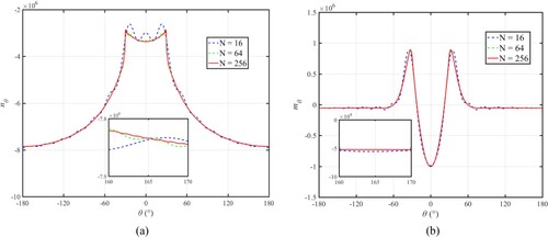
Figure 9. Evolution of the approximate solution for the circumferential stress of the outer lining surface.
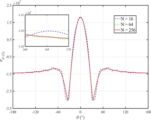
Figure 10. Evolution of the overall stress and radial stress of the rock reinforced by end-anchored bolts: (a) hard rock reinforced by end-anchored bolts ρ = r, (b) hard rock ρ = r.
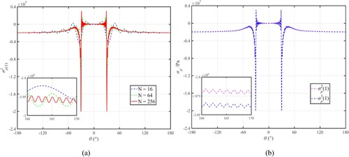
Figure 11. Radial stress evolution of the rock reinforced by end-anchored bolts at ρ = 1.05r.
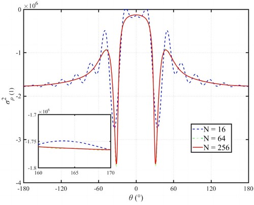
Figure 12. Evolution of lining surface load and series order: (a) lining surface load at ρ = R; (b) surface load series order.
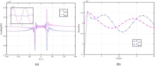
Figure 13. Evolution of lining displacement and displacement order: (a) lining displacement at ρ = r; (b) displacement order.
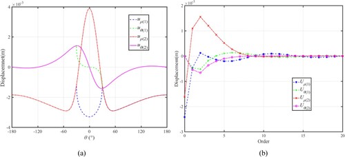
Figure 14. Evolution of the lining circumferential stress distribution.
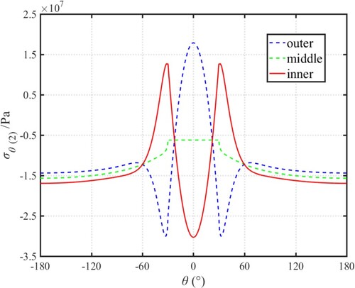
Figure 15. Evolution of tangential stress of the lining with different void sizes.
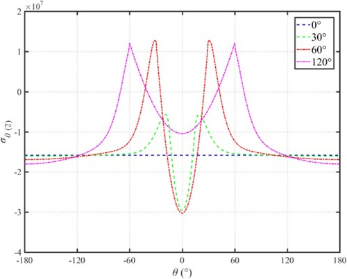
Figure 16. Evolution of lining stress and displacement: (a) hard rock lining displacement; (b) soft rock lining displacement; (c) Tangential stress of hard rock lining; (d) Tangential stress of soft rock lining.
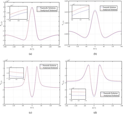
Figure 17. Evolution of the lining reaction force for the tunnel with double voids behind the lining.
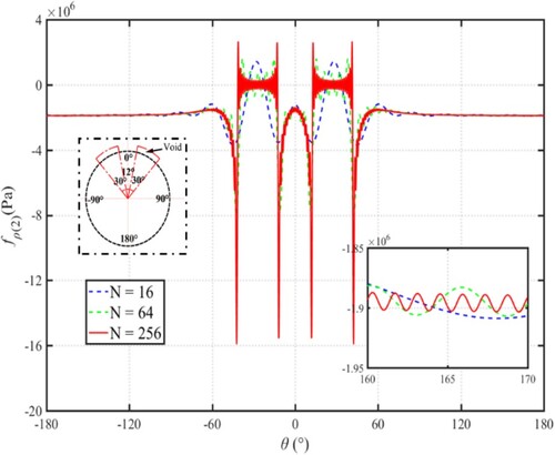
Figure 18. Evolution of the lining displacement for the tunnel with double voids behind the lining
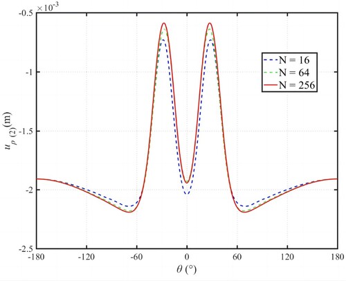
Figure 19. Evolution of the lining axial force and bending moment for the tunnel with double voids behind the lining. (a) lining axial force, (b) lining bending moment.
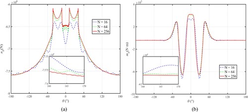
Figure 20. Evolution of the lining circumference stress for tunnel with double voids behind the lining.
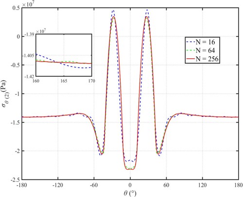
Figure 21. Evolution of the rock radial stress for tunnel with double voids behind the lining (ρ = 1.05r).
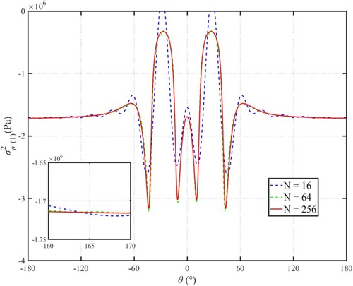
Figure 22. Evolution of the lining surface stress and Series order for the tunnel with double voids behind the lining. (a) lining surface stress at ρ = R, (b) Series order.
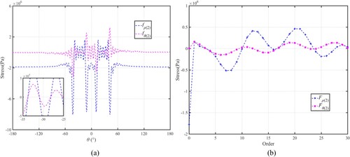
Figure 23. Evolution of lining and rock displacement for the tunnel with double voids behind the lining. (a) lining displacement at ρ = r, (b) Series order.
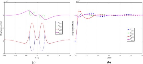
Figure 24. Evolution of lining reaction force for the end-anchored tunnel with single and double voids behind the lining.
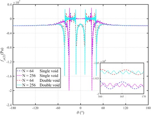
Figure 25. Evolution of lining displacement for the end-anchored tunnel with double voids behind the lining.
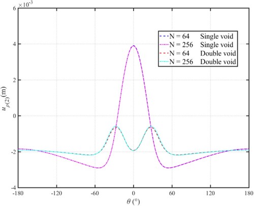
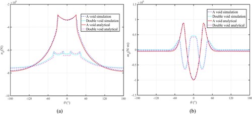
Figure 26. Evolution of lining axial force and bending moment for the tunnel with single void and double voids behind the lining. (a) lining axial force, (b) bending moment.
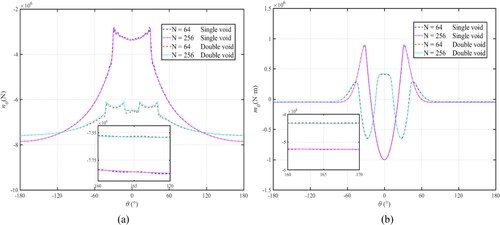
Figure 27. FLAC3D numerical simulation model setup.
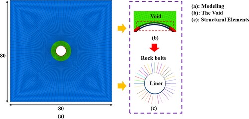
Table 3. Rock bolt material properties.
Figure 28. Simulation results with single void (left column) and with double voids (right column). (a) rock radial stress, (b) rock radial displacement, (c) lining circumferential axial force, and (d) ling bending moment.
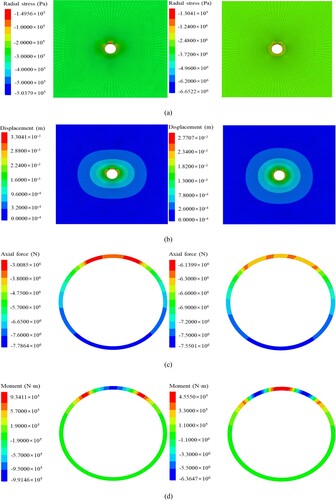
Figure 29. Evolution of approximate and simulated solutions: (a) radial stress; (b) radial displacement.
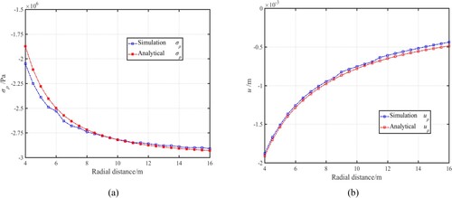
Figure 30. Evolution of approximate solution and simulated solution: (a) lining bending moment; (b) lining axial force.