Figures & data
Figure 1. Physical domain for different thermal source locations of the corrugated cylinder.
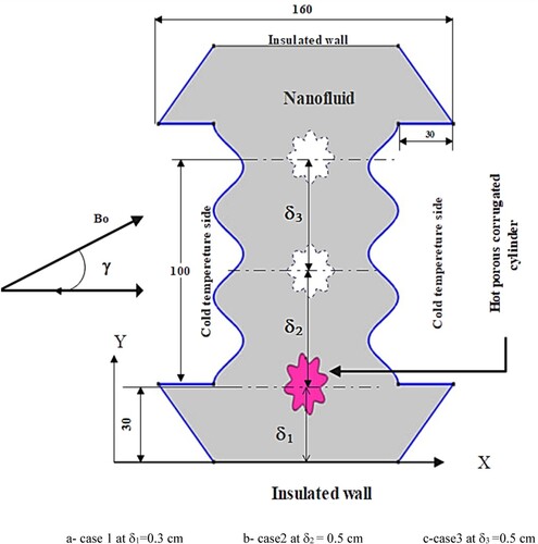
Table 1. Thermophysical properties of Nanoparticle and basic fluid at T = 250 C [Citation32].
Table 2. Coefficients included in non-dimensional G.E.
Figure 2. Mesh generation of proposed geometry.
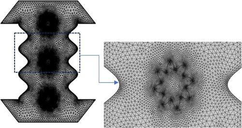
Table 3. Sensitivity of Grid generation on the dimensionless value of Nusselt number.
Table 4. Validation of Nuavg at φ = 0.04, Ha = 80 of the current study with Malekpour et al.[Citation37].
Figure 3. Validation with significant researchers in terms Nu and Ra.
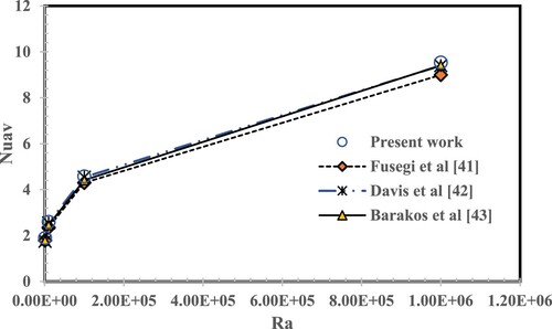
Figure 4. Validation in terms of streamlines of CFD results for present work and Hussain and Rahomey [Citation38].
![Figure 4. Validation in terms of streamlines of CFD results for present work and Hussain and Rahomey [Citation38].](/cms/asset/6bb2db3e-f461-4f6f-9218-65b5f20889bd/tusc_a_2335685_f0004_oc.jpg)
Figure 5. (a) validation the dynamic viscosity ratio with experimental of Ho et al. [Citation39] (b) validation of thermal conductivity ratio with Chon et al. [Citation40].
![Figure 5. (a) validation the dynamic viscosity ratio with experimental of Ho et al. [Citation39] (b) validation of thermal conductivity ratio with Chon et al. [Citation40].](/cms/asset/95441d7d-af7a-472b-804b-a8b06838465f/tusc_a_2335685_f0005_oc.jpg)
Figure 6. Iso thermal contour at different Ra number (Ha = 60 and Da = 10−3).
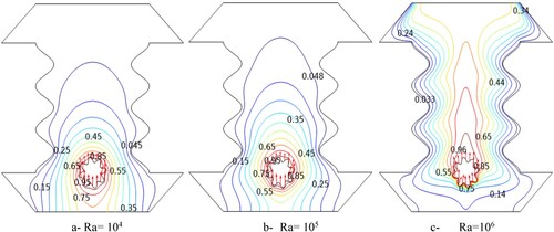
Figure 7. Stream functions for different Ra number (at Ha = 60 and Da = 10−3).
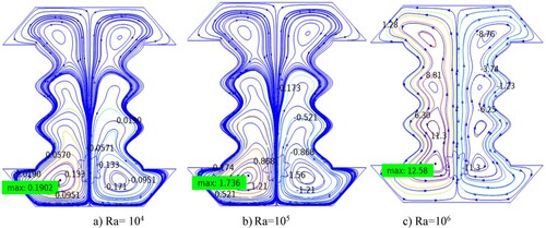
Figure 8. Isothermal counter for different Ha number (at Ra = 106, and Da = 10−3).
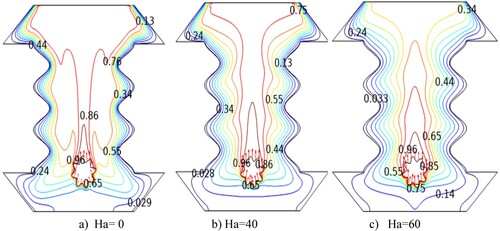
Figure 9. Stream function counter for different Ha numbers (at Ra = 106, and Da = 10−3).
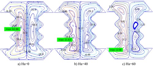
Figure 10. The isothermal counter varies the magnetic source’s inclination angle (Ha = 60, Ra = 106, Da = 10−3, and δ = 0.3).
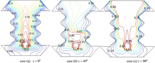
Figure 11. The stream function counter varies the magnetic source’s inclination angle (Ha = 60, Ra = 106, Da = 10−3 and δ = 0.3).
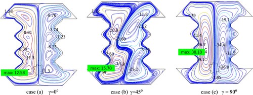
Figure 12. Isothermal counter for different Da numbers (at Ra = 106 and Ha = 60).
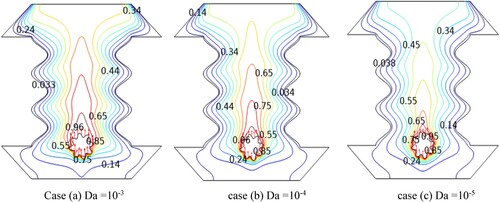
Figure 13. Stream function counter for different Da numbers (at Ra = 106 and Ha = 60).
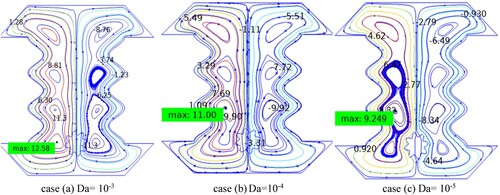
Figure 14. The isothermal counter varies at different positions (Ha = 60, Ra = 106, Da = 10−3).
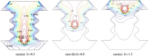
Figure 15. Stream function varies at different positions (Ha = 60, Ra = 106, Da = 10−3).
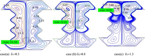
Figure 16. Values of Nu interfaces with ϕ for different locations of the hot cylinder at Ha = 60, Ra = 106, and γ = 900.
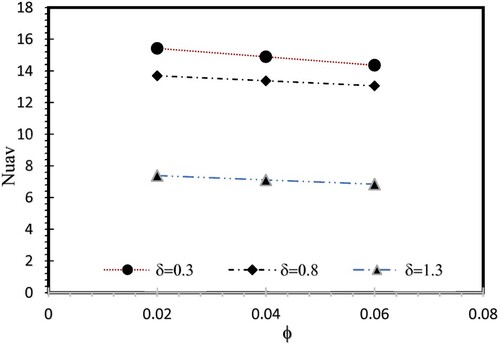
Figure 17. Nu interfaces with γ, on the first cylinder at δ = 0.3, at different volume fractions Ra = 106 and Ha = 60, Da = 10−3.
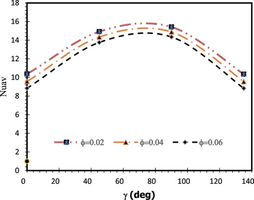
Figure 18. Nu interfaces with Ha on the first cylinder at δ = 0.3, at a different angle of inclination, Ra = 106 and ϕ = 0.02, Da = 10−3.
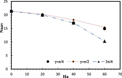
Figure 19. Nu interfaces with volume fraction on the first cylinder at δ = 0.3, at different Ra, Ha = 60 and Da = 10−3,γ=p/2.
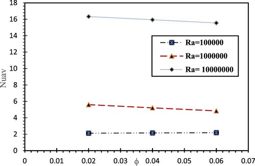
Figure 20. Nu interfaces Ra on the first cylinder at δ = 0.3, at different Da, Ha = 20 and, γ = 0.
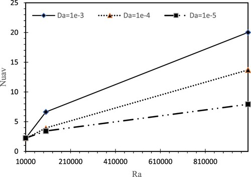
Figure 21. Nu varies with the number of undulations of the hot corrugated cylinder at δ = 0.3 (Ra = 106, Ha = 30, Da = 10−3, ϕ=0.06, γ = 00).
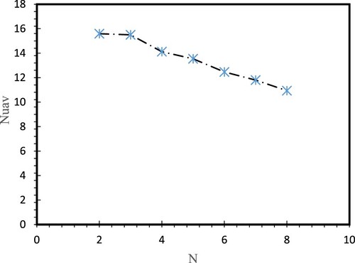
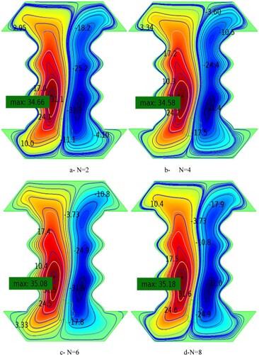
Figure 22. Contour shows the max stream function for different numbers of undulations.