Figures & data
Figure 1. Details tested beams (G3: G7).
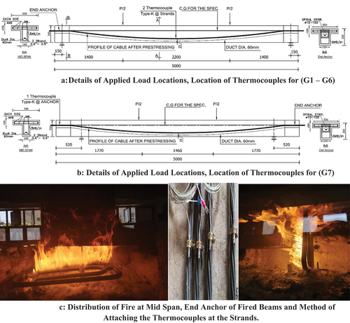
Table 1. Details of tested specimens.
Figure 2. Test setup for Both types of tested beams.
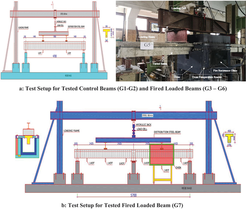
Figure 3. Thermal insulation proposed system with the unbonded pre-stressing strands and end anchor.
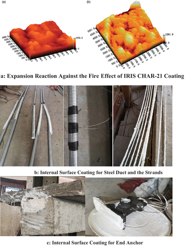
Figure 4. Mode of failure and failure crack pattern of control beams (G1, G2).
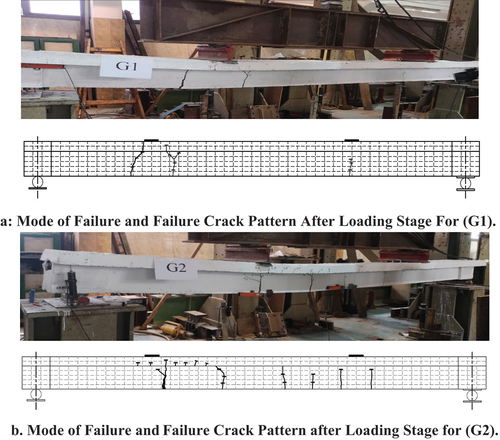
Table 2. Value of service loads, deflections at initial cracking loads and deflection, strand temperature at initial cracking, after 180 min.
Figure 5. Strand temperature with fire exposure time and end anchor thermal behavior with thermal insulation coating.
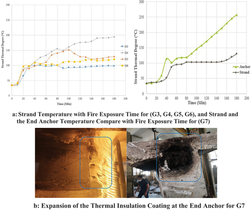
Figure 6. Load - deflection relationship for all the tested beams.
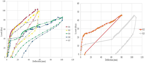
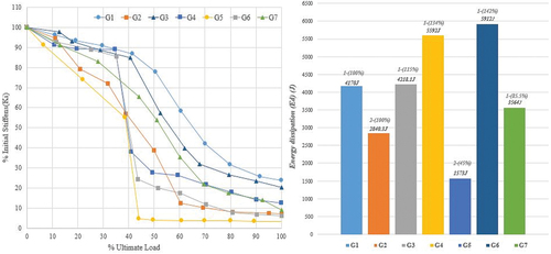
Table 3. Value of loads, deflections at initial and post cracking stages for the tested specimens, initial stiffness (Ki) and stiffness at 50% of the failure point (K-50%).
Figure 7. Beam deflection with fire exposure time for (G3, G4, G5, G6, G7).
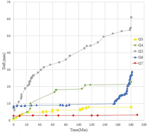
Figure 8. Crack pattern and the recorded outgoing water from (G3, G4).
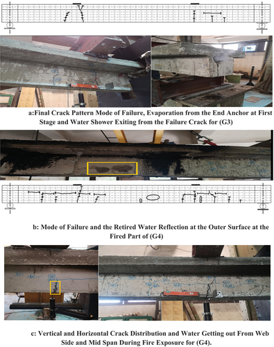
Figure 9. Loading system, final crack pattern and mode of failure of (G5, G6).
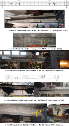
Figure 10. Loading system, final crack pattern and mode of failure of (G7).
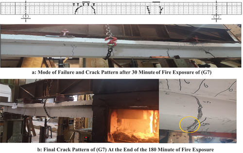
Figure 11. Stiffness degradation over the test lifetime and specimens energy dissipation (ed).