233
Views
6
CrossRef citations to date
0
Altmetric
Original Articles

Evaluating time-dependent heat fluxes using artificial neural networks

, &
Pages 97-109 | Received 15 Apr 2004, Accepted 08 Nov 2004, Published online: 21 Aug 2006

Figures & data

Figure 1. Schematic of the studied structure.

Figure 1. Schematic of the studied structure.

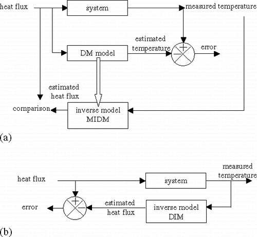
Figure 2. Calculation procedures (a) inversing the direct model and (b) finding an inverse model.

Figure 2. Calculation procedures (a) inversing the direct model and (b) finding an inverse model.

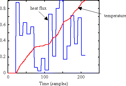
Figure 3. Example of the response of the structure (direct problem).

Figure 3. Example of the response of the structure (direct problem).

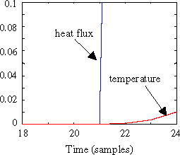
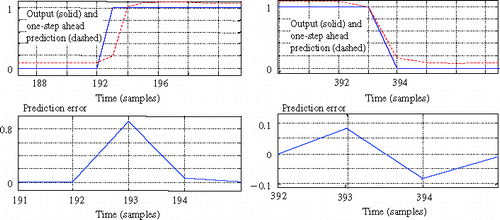
Figure 4. Detailed view of the response.

Figure 4. Detailed view of the response.

Figure 5. Standard architecture for the direct problem.

Figure 5. Standard architecture for the direct problem.

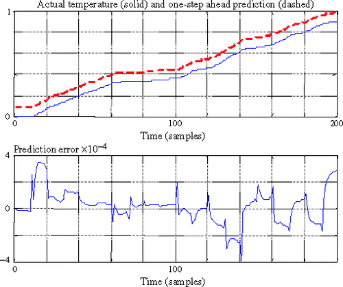
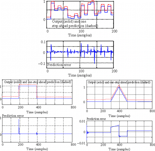
Figure 6. Example of the prediction and prediction error of the model for the direct problem.

Figure 6. Example of the prediction and prediction error of the model for the direct problem.

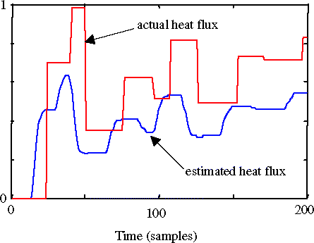
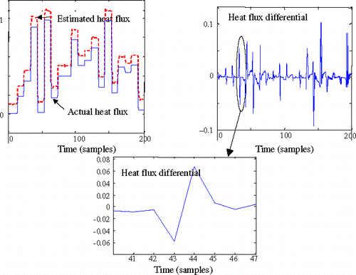
Figure 7. Example of results after inversion (for an unknown heat flux sequence).

Figure 7. Example of results after inversion (for an unknown heat flux sequence).

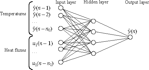
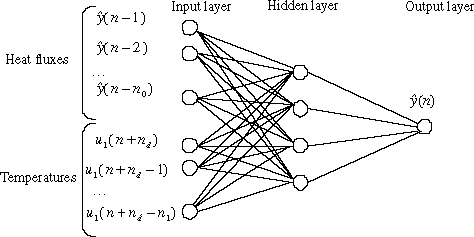
Figure 8. General architecture of the tested neural networks for the inverse model (DIM model).

Figure 8. General architecture of the tested neural networks for the inverse model (DIM model).

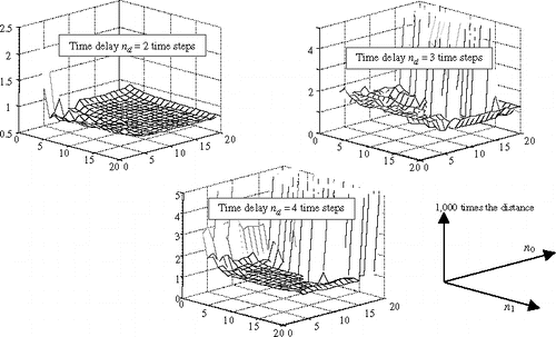
Figure 9. Sum of prediction errors for various time delays.

Figure 9. Sum of prediction errors for various time delays.

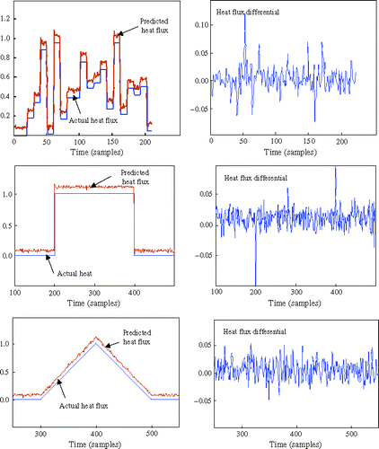
Figure 10. Predicted heat flux and prediction errors during the test phase.

Figure 10. Predicted heat flux and prediction errors during the test phase.

Figure 11. Detailed views of the predicted heat flux and the prediction error for the rectangular pulse.

Figure 11. Detailed views of the predicted heat flux and the prediction error for the rectangular pulse.

Figure 12. Prediction error during the validation phase.

Figure 12. Prediction error during the validation phase.

Figure 13. Detailed views of the predicted heat flux and the prediction error when noise is added to the temperatures.

Figure 13. Detailed views of the predicted heat flux and the prediction error when noise is added to the temperatures.

Figure 14. Coupled neural models for the final validation.

Figure 14. Coupled neural models for the final validation.

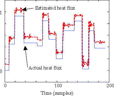
Figure 15. Comparison of actual and estimated heat fluxes when coupled neural models are used.

Figure 15. Comparison of actual and estimated heat fluxes when coupled neural models are used.

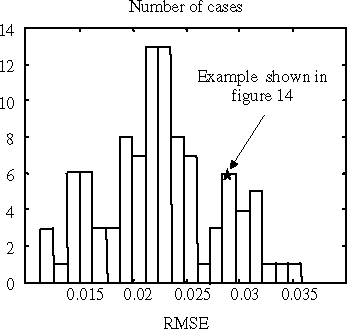
Figure 16. Histogram of the RMSE for the 100 validation cases.

Figure 16. Histogram of the RMSE for the 100 validation cases.

Reprints and Corporate Permissions

Please note: Selecting permissions does not provide access to the full text of the article, please see our help page How do I view content?

To request a reprint or corporate permissions for this article, please click on the relevant link below:

Academic Permissions

Please note: Selecting permissions does not provide access to the full text of the article, please see our help page How do I view content?

Obtain permissions instantly via Rightslink by clicking on the button below:

If you are unable to obtain permissions via Rightslink, please complete and submit this Permissions form. For more information, please visit our Permissions help page.