197
Views
1
CrossRef citations to date
0
Altmetric
Original Articles

Determination of dynamic load distributions applied to Kirchhoff plates based on FEM and numerical Laplace transformation method

Pages 485-506 | Received 26 Mar 2004, Accepted 21 Jan 2005, Published online: 26 Jan 2007

Figures & data

Figure 1. Adini element.

Figure 1. Adini element.

Figure 2. Initial FEM mesh division (8 × 8) of the whole plate region.

Figure 2. Initial FEM mesh division (8 × 8) of the whole plate region.

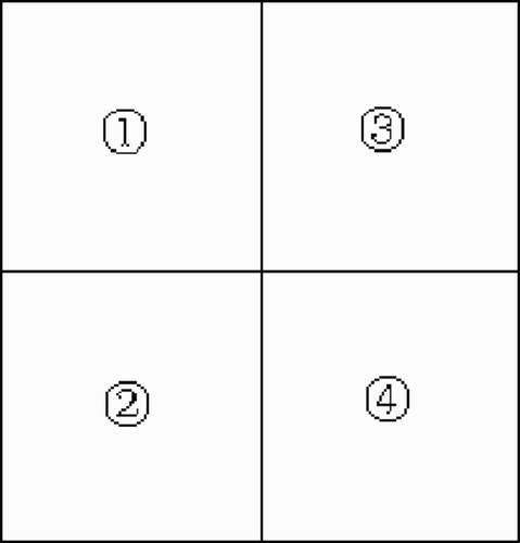
Figure 3. The square plate divided by the same four substructures.

Figure 3. The square plate divided by the same four substructures.

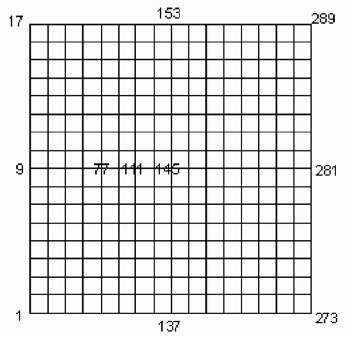
Figure 4. Refined FEM mesh division (16 × 16) of the whole plate region.

Figure 4. Refined FEM mesh division (16 × 16) of the whole plate region.

Figure 5. The exact time histories of the dynamic load on the 9, 77, 111, 145 nodal points (see ), which are represented by the dotted line (···), dash–dot line (– -), dashed line (— —) and solid line (—) respectively.
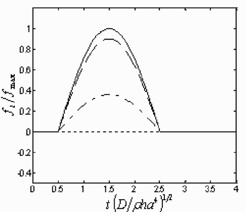
Figure 5. The exact time histories of the dynamic load on the 9, 77, 111, 145 nodal points (see figure 4), which are represented by the dotted line (···), dash–dot line (– -), dashed line (— —) and solid line (—) respectively.
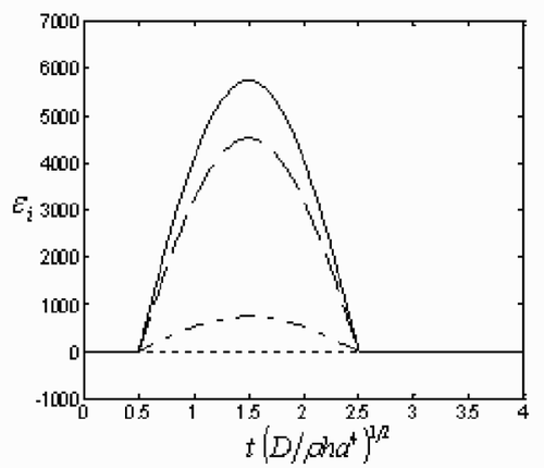
Figure 6. The time histories of the strains on the 9, 77, 111, 145 nodal points, which are represented by the dotted line (···), dash–dot line (– -), dashed line (— —) and solid line (—) respectively.

Figure 6. The time histories of the strains on the 9, 77, 111, 145 nodal points, which are represented by the dotted line (···), dash–dot line (– -), dashed line (— —) and solid line (—) respectively.

Figure 7. A square Kirchhoff plate with all its edges clamped subjected to a transverse load.

Figure 7. A square Kirchhoff plate with all its edges clamped subjected to a transverse load.

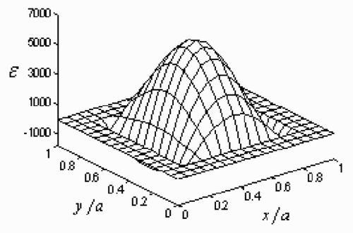
Figure 8. The strain distributions on the plate implemented as the additional information.

Figure 8. The strain distributions on the plate implemented as the additional information.

Figure 9. The directly derived time histories of dynamic load on the 5, 23, 32, 41 nodal points (see ), which are represented by dotted line (…), dash–dot line (—-), dashed line (— —) and solid line (—) respectively on the plot. Here FEM mesh division of the plate region is 8 × 8. The noise levels are: (a) 0%; (b) 0.001%.
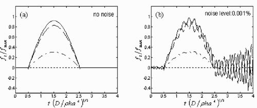
Figure 9. The directly derived time histories of dynamic load on the 5, 23, 32, 41 nodal points (see figure 2), which are represented by dotted line (…), dash–dot line (—-), dashed line (— —) and solid line (—) respectively on the plot. Here FEM mesh division of the plate region is 8 × 8. The noise levels are: (a) 0%; (b) 0.001%.

Figure 10. The regularized time histories of dynamic load on the 5, 23, 32, 41 nodal points (see ), which are represented by the dotted line (···), dash–dot line (– -), dashed line (— —) and solid line (—) respectively on the plot. Here FEM mesh division of the plate region is 8 × 8. The noise levels are: (a) 0%, (b) 1%, (c) 2% and (d) 3%.
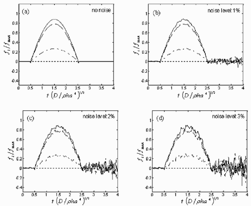
Figure 10. The regularized time histories of dynamic load on the 5, 23, 32, 41 nodal points (see Figure 2), which are represented by the dotted line (···), dash–dot line (– -), dashed line (— —) and solid line (—) respectively on the plot. Here FEM mesh division of the plate region is 8 × 8. The noise levels are: (a) 0%, (b) 1%, (c) 2% and (d) 3%.

Figure 11. The regularized time histories of dynamic load at the left bottom end point P and the center point Q of the plate (shown in subplot (a)), which are represented by the dotted line (…) and solid line (—) respectively. FEM mesh divisions are: (b) 6 × 6; (c) 8 × 8; (d) 10 × 10.
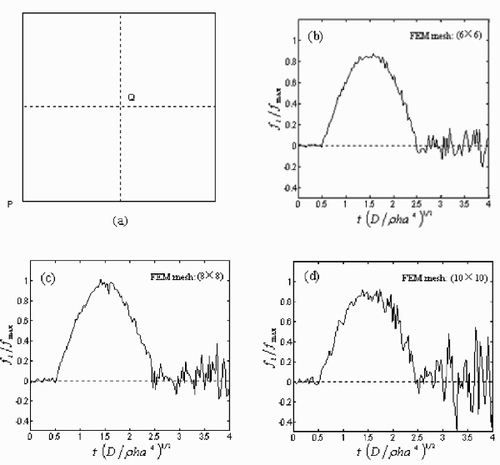
Figure 11. The regularized time histories of dynamic load at the left bottom end point P and the center point Q of the plate (shown in subplot (a)), which are represented by the dotted line (…) and solid line (—) respectively. FEM mesh divisions are: (b) 6 × 6; (c) 8 × 8; (d) 10 × 10.

Figure 12. The regularized time histories of dynamic load on the 9, 77, 111, 145 nodal points (see ), which are represented by the dotted line (···), dash–dot line (—-), dashed line (— —) and solid line (—) respectively on the plot. Here FEM mesh division of the plate region is 16 × 16. The noise levels are: (a) 0%; (b) 1%; (c) 2%; (d) 3%.
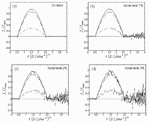
Figure 12. The regularized time histories of dynamic load on the 9, 77, 111, 145 nodal points (see figure 4), which are represented by the dotted line (···), dash–dot line (—-), dashed line (— —) and solid line (—) respectively on the plot. Here FEM mesh division of the plate region is 16 × 16. The noise levels are: (a) 0%; (b) 1%; (c) 2%; (d) 3%.

Figure 13. The regularized time histories of dynamic load on the 5, 23, 32, 41 nodal points (see ), which are represented by the dotted line (···), dash–dot line (—-), dashed line (— —) and solid line (—) respectively on the plot. γ, the real part of Laplace parameter p, is appointed as: (a) 2/T; (b) 3/T; (c) 4/T; (d) 2Π/T. The white noise level is 3%.
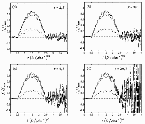
Figure 13. The regularized time histories of dynamic load on the 5, 23, 32, 41 nodal points (see figure 2), which are represented by the dotted line (···), dash–dot line (—-), dashed line (— —) and solid line (—) respectively on the plot. γ, the real part of Laplace parameter p, is appointed as: (a) 2/T; (b) 3/T; (c) 4/T; (d) 2Π/T. The white noise level is 3%.

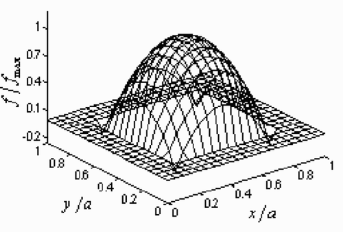
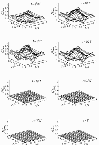
Figure 14. The exact dynamic load distributions applied to the square Kirchhoff plate at eight different times.
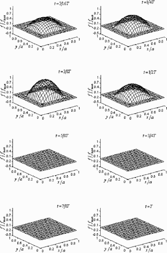
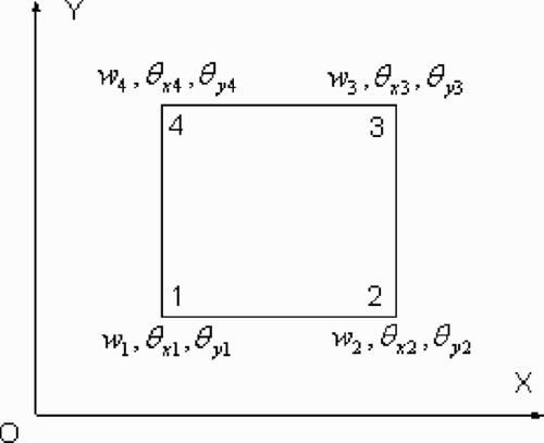
Figure 14. The exact dynamic load distributions applied to the square Kirchhoff plate at eight different times.
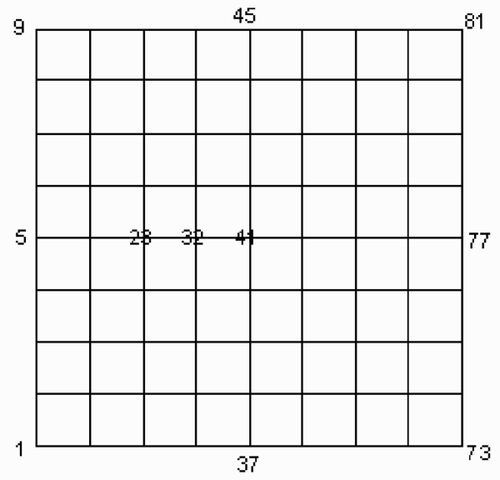
Figure 15. The regularized dynamic load distributions applied to the square Kirchhoff plate at eight times without noise added.

Figure 15. The regularized dynamic load distributions applied to the square Kirchhoff plate at eight times without noise added.

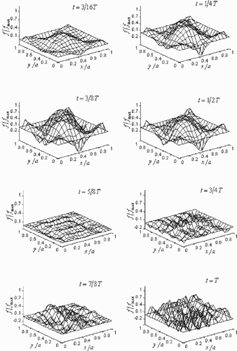
Figure 16. The regularized dynamic load distributions applied to the square Kirchhoff plate at eight times with 3% white noise.

Figure 16. The regularized dynamic load distributions applied to the square Kirchhoff plate at eight times with 3% white noise.

Reprints and Corporate Permissions

Please note: Selecting permissions does not provide access to the full text of the article, please see our help page How do I view content?

To request a reprint or corporate permissions for this article, please click on the relevant link below:

Academic Permissions

Please note: Selecting permissions does not provide access to the full text of the article, please see our help page How do I view content?

Obtain permissions instantly via Rightslink by clicking on the button below:

If you are unable to obtain permissions via Rightslink, please complete and submit this Permissions form. For more information, please visit our Permissions help page.