333
Views
26
CrossRef citations to date
0
Altmetric
Original Articles

Optimization tools in the analysis of micro-textured lubricated devices

, &
Pages 365-378 | Received 10 Jan 2005, Accepted 02 May 2005, Published online: 26 Jan 2007

Figures & data

Figure 1. Schematic view of a slider.

Figure 1. Schematic view of a slider.

Figure 2. Schematic view of the dimples and an individual cell with its system of coordinates.

Figure 2. Schematic view of the dimples and an individual cell with its system of coordinates.

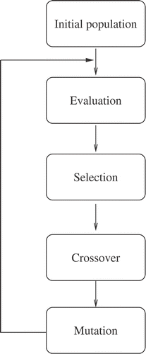
Figure 3. Flow chart of the genetic algorithm.

Figure 3. Flow chart of the genetic algorithm.

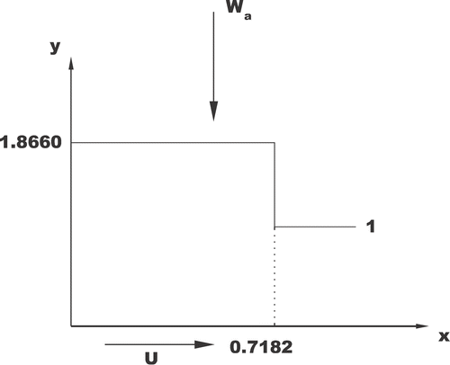
Figure 4. Non-dimensional Rayleigh step.

Figure 4. Non-dimensional Rayleigh step.

Figure 5. Results of the GENESIS code compared to the optimal Rayleigh step. Left: Case 1, Right: Case 2.
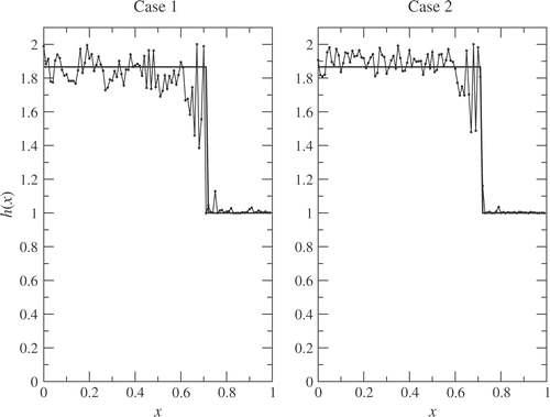
Figure 5. Results of the GENESIS code compared to the optimal Rayleigh step. Left: Case 1, Right: Case 2.

Table 1. Results of the GENESIS code compared to the exact ones, indicating the number of evaluations (Case 3).

Table 2. Relative load capacity obtained with the GENESIS code using 50, 100 and 200 variables to define the film thickness h.

Figure 6. History of the objective function along algorithmic iterations (relative to the exact optimum). The mutation rate constant is set to the default value of the GENESIS code, 0.001. The tics in the vertical axis have a spacing of 0.1.
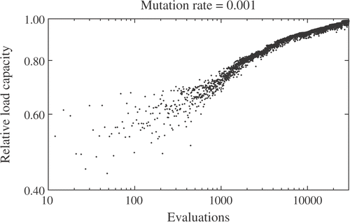
Figure 6. History of the objective function along algorithmic iterations (relative to the exact optimum). The mutation rate constant is set to the default value of the GENESIS code, 0.001. The tics in the vertical axis have a spacing of 0.1.

Figure 7. History of the objective function along algorithmic iterations (relative to the exact optimum). The mutation rate constant is set to 0.01.
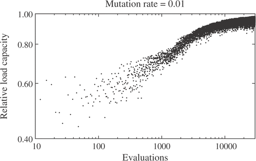
Figure 7. History of the objective function along algorithmic iterations (relative to the exact optimum). The mutation rate constant is set to 0.01.

Figure 8. History of the objective function along algorithmic iterations (relative to the exact optimum). The mutation rate constant is set to 0.1, a value that is too high to attain convergence.
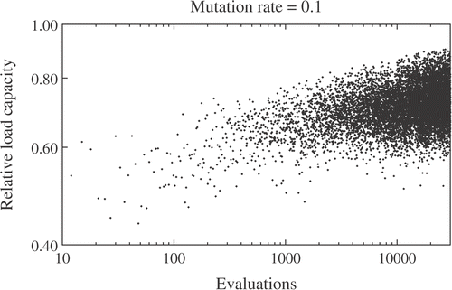
Figure 8. History of the objective function along algorithmic iterations (relative to the exact optimum). The mutation rate constant is set to 0.1, a value that is too high to attain convergence.

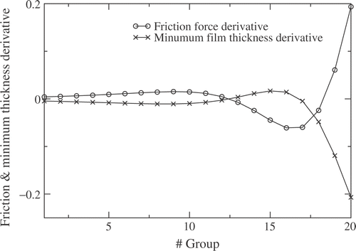
Figure 9. Friction force and minimum film thickness derivatives along the slider.

Figure 9. Friction force and minimum film thickness derivatives along the slider.

Figure 10. Relative friction force and minimum film thickness. Evolution along the optimization process. Notice that a 4% decrease in friction, together with a 2% increase in minimum film thickness, is attained.
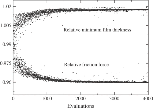
Figure 10. Relative friction force and minimum film thickness. Evolution along the optimization process. Notice that a 4% decrease in friction, together with a 2% increase in minimum film thickness, is attained.

Figure 11. Optimized textures for two different non-dimensional loads: 0.06 (top) and 0.006 (bottom).
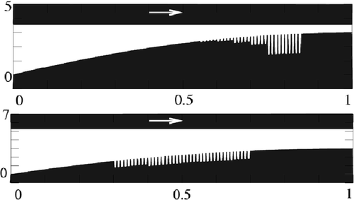
Figure 11. Optimized textures for two different non-dimensional loads: 0.06 (top) and 0.006 (bottom).

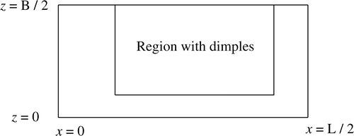
Figure 12. Scheme showing the region in which dimples are introduced in the finite-width case.

Figure 12. Scheme showing the region in which dimples are introduced in the finite-width case.

Figure 13. Pressure distribution when a uniform texture is introduced in the region indicated in .

Figure 13. Pressure distribution when a uniform texture is introduced in the region indicated in figure 12.

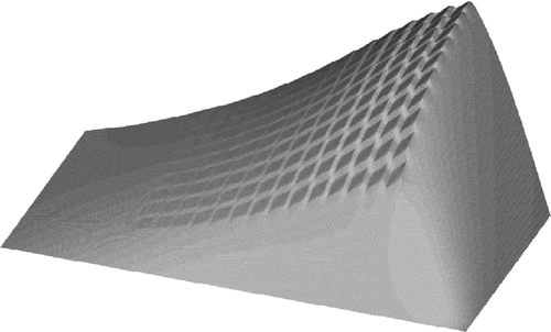
Figure 14. A 3D view of depth distribution of the optimized texture after 3000 evaluations of the objective function. The maximum depth is 1.292, the minimum one is 0.085.
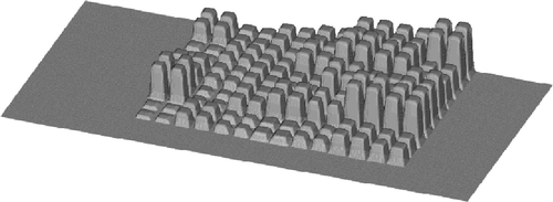
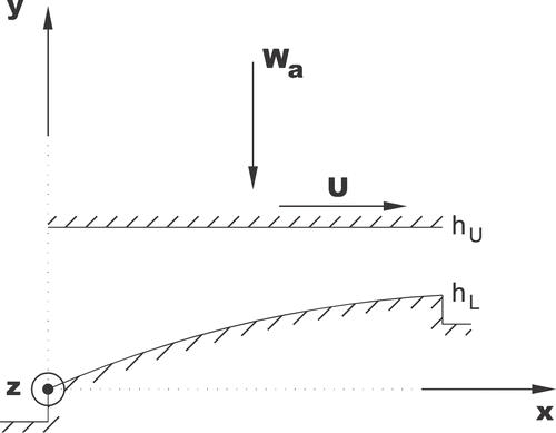
Figure 14. A 3D view of depth distribution of the optimized texture after 3000 evaluations of the objective function. The maximum depth is 1.292, the minimum one is 0.085.
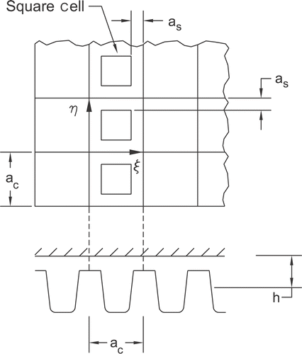
Figure 15. Two 3D views of depth distribution of the optimized texture obtained after 18,000 evaluations of the objective function. The maximum depth is 1.294, the minimum one is 0.0025.

Figure 15. Two 3D views of depth distribution of the optimized texture obtained after 18,000 evaluations of the objective function. The maximum depth is 1.294, the minimum one is 0.0025.

Figure 16. Optimized texture with the depth shown by means of color zones. The maximum depth is 1.294 (brighter), the minimum one is 0.0025 (darker).

Figure 16. Optimized texture with the depth shown by means of color zones. The maximum depth is 1.294 (brighter), the minimum one is 0.0025 (darker).

Reprints and Corporate Permissions

Please note: Selecting permissions does not provide access to the full text of the article, please see our help page How do I view content?

To request a reprint or corporate permissions for this article, please click on the relevant link below:

Academic Permissions

Please note: Selecting permissions does not provide access to the full text of the article, please see our help page How do I view content?

Obtain permissions instantly via Rightslink by clicking on the button below:

If you are unable to obtain permissions via Rightslink, please complete and submit this Permissions form. For more information, please visit our Permissions help page.