Figures & data
Table 1. Inaccuracy of estimates of volume fraction using inverse Maxwell Garnett formula (2) for composites with different microgeometries
Figure 1. Reconstruction of Padé coefficients (a) and of the spectral measure μ (b) for air–bubble–water mixtures with spherical and ellipsoidal inclusions (air volume fraction f = 15%).
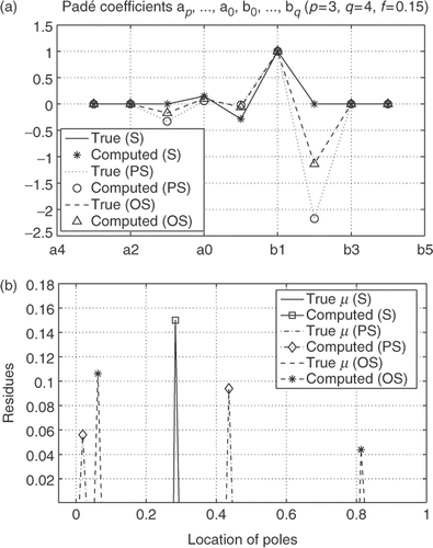
Figure 2. True and computed effective permittivity, real ε* (a) and imaginary ε* (b), for mixtures of air bubbles and water for various types of inclusions (ω = 0.001–100 GHz, f = 15%).
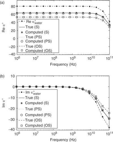
Table 2. Computed air volume fractions, residues, and poles for mixtures of air PS inclusions and water (p = 3, q = 4, ω = 0.001–100 GHz, N = 15, ax = 1.0, ay = az = 0.1)
Table 3. Computed air volume fractions, residues, and poles for mixtures of OS inclusions of air in water (p = 3, q = 4, ω = 0.001–100 GHz, N = 15, ax = ay = 1.0, az = 0.1)
Figure 3. True and computed ε* (a) and F(s) (b) for mixtures of air bubbles in water with frequency as parameter (f = 6, 12, 18, 25%).
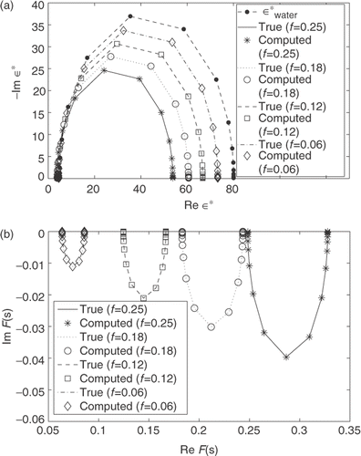
Figure 4. (a): True and computed imaginary part of ε*. (b): Reconstruction of poles and residues of the spectral measure μ for mixtures of air bubbles in water (f = 6, 12, 18, 25%).
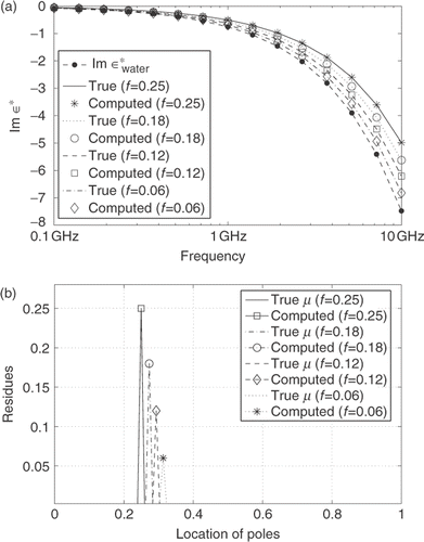
Table 4. Computed air volume fractions, residues, and poles for mixtures of water with air PS inclusions for temperature-dependent model (p = 2, q = 3, ω = 9 GHz, t = 16–24°C, N = 12, ax = 1.0, ay = az = 0.2)
Table 5. Computed air volume fractions, residues, and poles for mixtures of air bubbles and water for OS inclusions model for temperature-dependent permittivity (p = 2, q = 3, ω = 9 GHz, t = 16–24°C, N = 12, ax = ay = 1.0, az = 0.2)
Figure 5. Reconstruction results for mixtures of air bubbles and water for spherical and ellipsoidal shape of air inclusions using data in the temperature range t = 16–24°C for air volume fraction f = 8%. (a): true and computed imaginary part of the effective permittivity ε*. (b): reconstruction of the spectral function μ. The frequency of the applied field is ω = 9 GHz.
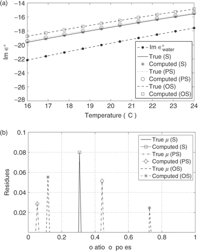
Figure 6. Reconstruction of Padé coefficients (a) and residues and poles of the spectral function μ (b) for mixtures of air bubbles in water (f = 5, 10, 16, 26%).
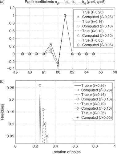
Figure 7. True and computed real ε* (a) and imaginary ε* (b) for mixtures of air bubbles in water for temperature ranging from 0°C to 70°C (ω = 9 GHz, f = 5, 10, 16, 26%).
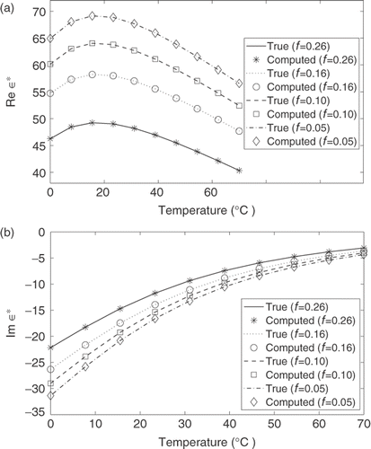
Figure 8. Results for air–bubble–ethanol mixtures modeled as composites with spherical or ellipsoidal inclusions; air volume fraction is f = 25%. (a): imaginary part of F(s). (b): reconstructed density of the spectral function μ.
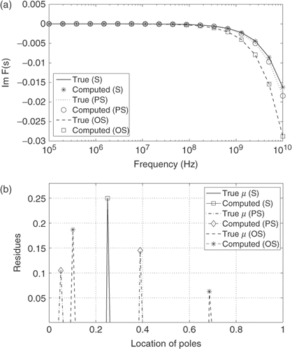
Table 6. Mixture of air bubbles and ethanol for model with PS inclusions. Computed air volume fractions, residues and poles of the spectral function (p = 4, q = 5, ω = 0.0001–10 GHz, N = 18, ax = 1.0, ay = ax = 0.2)
Table 7. Computed air volume fractions, residues and poles for mixtures of ethanol and air OS inclusions (p = 4, q = 5, ω = 0.0001–10 GHz, N = 18, ax = ay = 1.0, az = 0.2)
Figure 9. Reconstruction of Padé coefficients (a), residues and poles of spectral measure μ (b) for mixtures of air bubbles in ethanol with volume fractions f = 4, 8, 14, 28%.
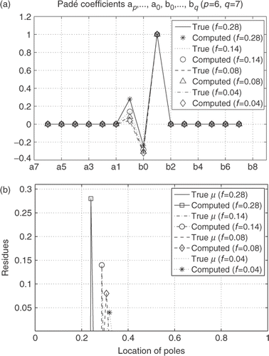
Figure 10. True and computed real ε* (a) and imaginary ε* (b) for mixtures of air bubbles in ethanol (volume fractions f = 4, 8, 14, 28%).
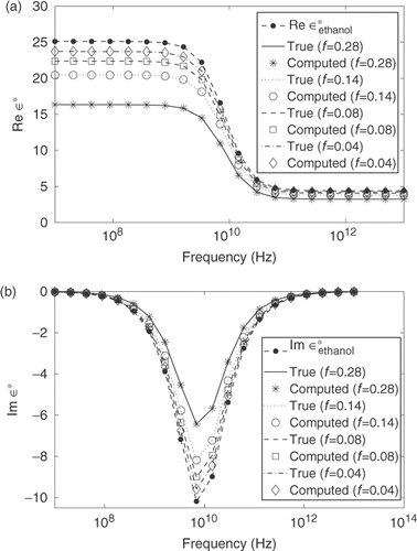
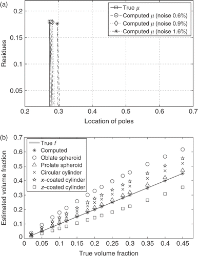
Figure 11. Figure (a) shows reconstruction of residues and poles of the spectral function μ for the mixture of air bubbles in water (true volume fraction f = 18%) with noise added to the input data. Figure (b) shows the volume fraction estimated using inverse MG formula (2) and computed with the presented method. The data are simulated using composites with different microgeometries. Stars * denote the volume fraction computed using the developed method.
