Figures & data
Figure 1. Simulation of elliptical surface with an incoming parallel flow by singularities superposition.
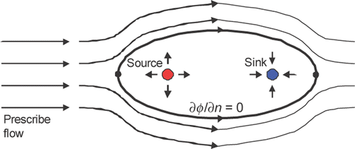
Figure 2. Geometric arrangement of points loads with a non-uniform elastic energy flow.
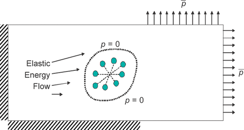
Figure 3. Geometry and conditions for square section with centred-circular hole. (a) Top cavity case; (b) Right-hand cavity case.
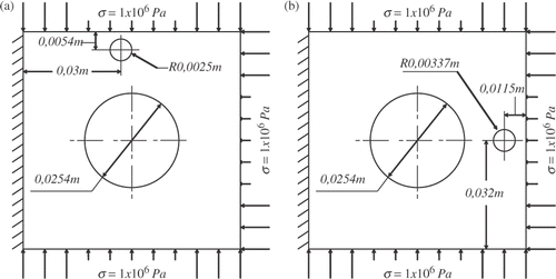
Figure 4. Discretization of square section with centred-hole cases. (a) Top cavity case; (b) Right-hand cavity case.
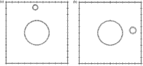
Figure 5. Displacement contours of square section with centred-hole cases. (a) Top cavity case; (b) Right-hand cavity case.
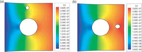
Figure 6. Evolution of the objective function for the square section with centred-hole case with the top cavity. (a) Evolution of objective function S1; (b) Evolution of objective function S2.
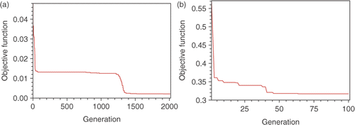
Figure 7. Evolution of the objective function for the square section with centred-hole case with the right-hand cavity. (a) Evolution of objective function S1; (b) Evolution of objective function S2.
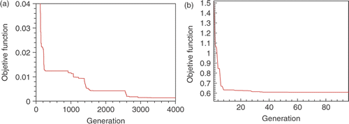
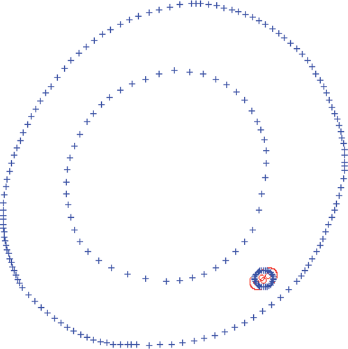
Figure 8. Cavity prediction after 2000 generations of the optimization process for the square section with centred-hole cases. (a) Top cavity case; (b) Right-hand cavity case.
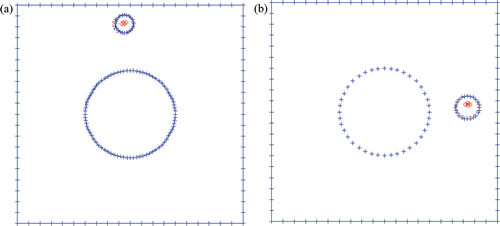
Figure 9. Geometry and boundary conditions for the femur cross-section case.
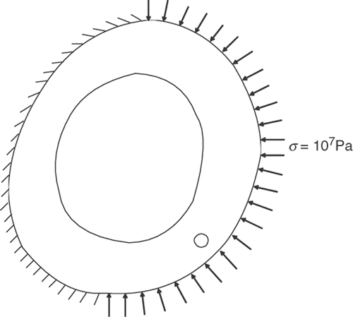
Figure 10. Displacement contours for the femur cross-section case.
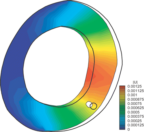
Figure 11. Evolution of the objective function for the femur cross-section case. (a) evolution of objective function S1; (b) evolution of objective function S2.
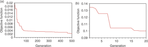
Figure 12. Cavity prediction after 500 generations of the optimization process for the femur cross-section cases.