Figures & data
Figure 1. Cascade notation and computational domain.
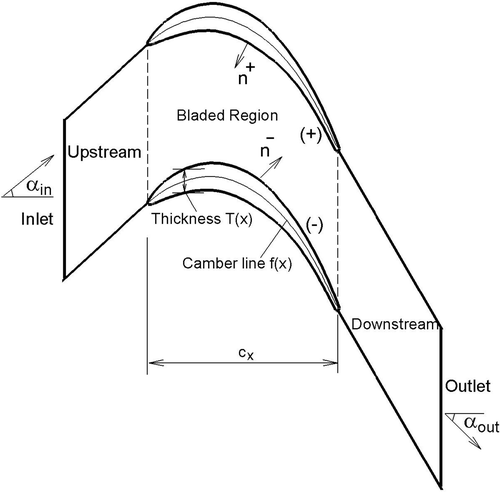
Figure 2. Schematic of the wall movement.
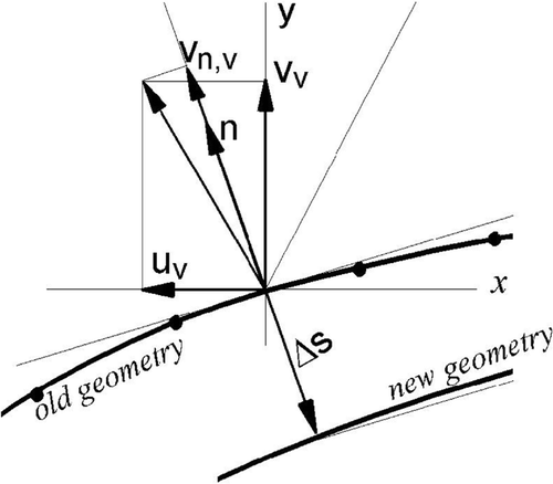
Figure 3. Inverse design flow chart.
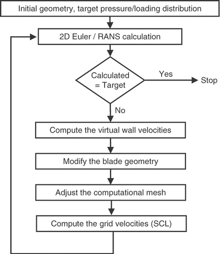
Figure 4. Mach contours for ONERA compressor cascade.
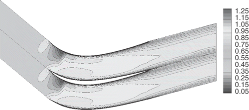
Table 1. ONERA cascade data and flow conditions.
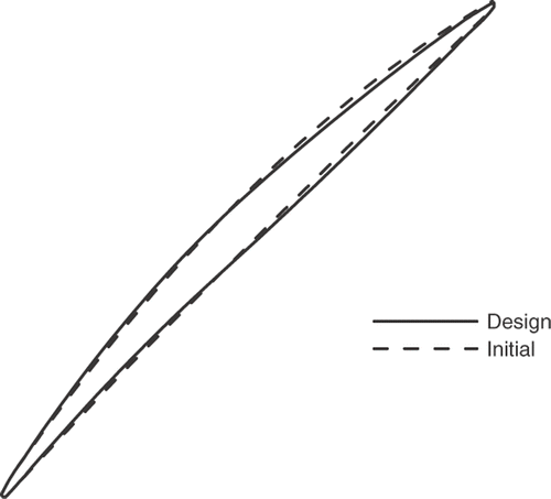
Figure 5. ONERA blade profiles.
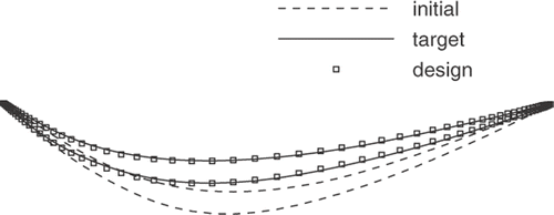
Figure 6. Loading distributions for ONERA compressor cascade design.
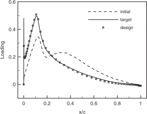
Figure 7. Isentropic Mach number distributions for ONERA compressor cascade design.
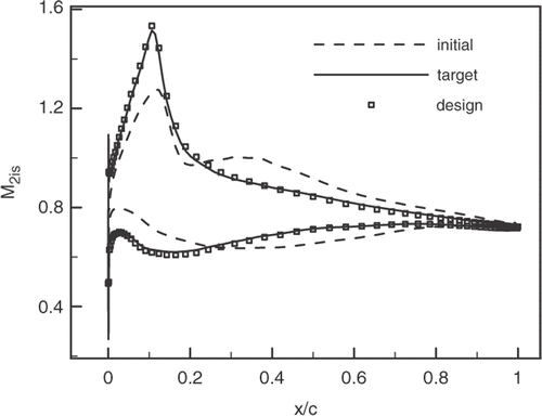
Figure 8. Convergence history of ONERA compressor cascade design.
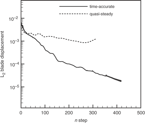
Table 2. DFVLR cascade data and flow conditions.
Figure 9. Mach number contours for DFVLR turbine cascade.
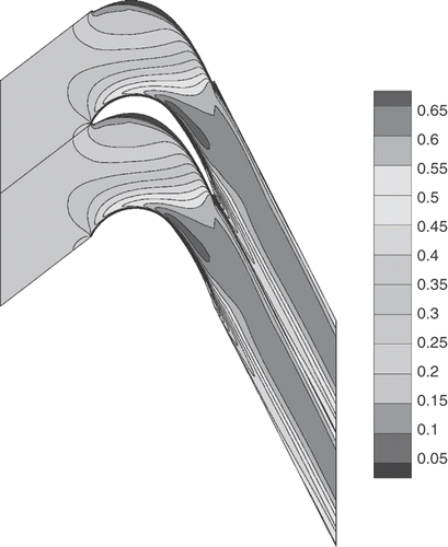
Figure 10. Loading distributions for DFVLR turbine cascade redesigns.
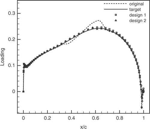
Figure 11. Pressure distributions for DFVLR turbine cascade redesigns.
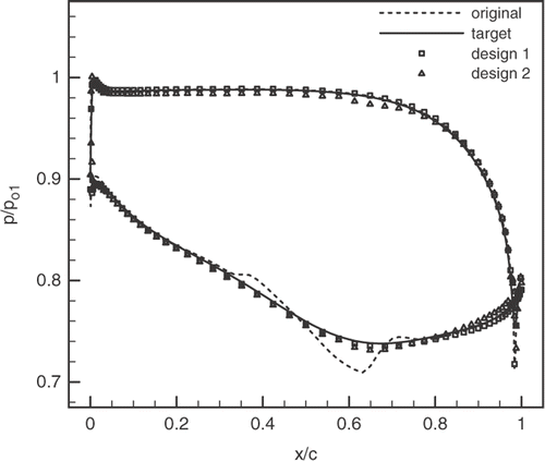
Figure 12. DFVLR turbine blade profiles.
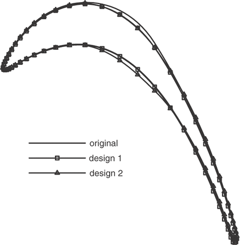
Table 3. Aerodynamic characteristics of DFVLR turbine redesign.
Table 4. NASA Rotor 67 data and flow conditions at midspan.
Figure 13. Mach contours for Rotor 67 midspan blade section.
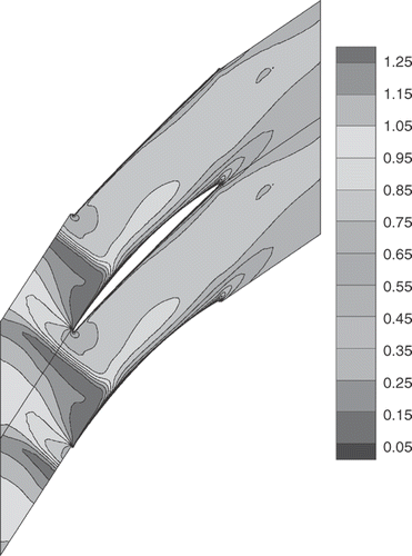
Figure 14. Loading distributions for Rotor 67 blade section redesign.
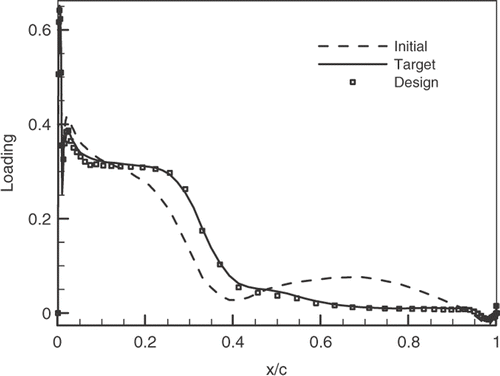
Figure 15. Pressure distributions for Rotor 67 midspan blade section redesign.
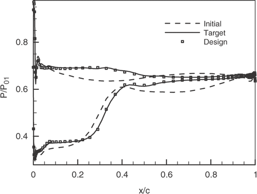
Figure 16. Rotor 67 midspan blade profiles.