444
Views
10
CrossRef citations to date
0
Altmetric
Original Articles

Three-dimensional viscous inverse method for axial blade design

, &
Pages 1019-1036 | Received 01 Oct 2008, Accepted 20 Apr 2009, Published online: 14 Oct 2009

Figures & data

Figure 1. Flow chart for numerical optimization, where the geometry modification is based on numerical minimization scheme, not the flow physics.
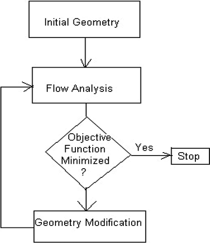
Figure 1. Flow chart for numerical optimization, where the geometry modification is based on numerical minimization scheme, not the flow physics.

Figure 2. Flow chart for hybrid inverse method, which requires convergent solutions for both analysis solver and inverse solver in each blade modification iteration (BC–boundary conditions).
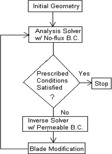
Figure 2. Flow chart for hybrid inverse method, which requires convergent solutions for both analysis solver and inverse solver in each blade modification iteration (BC–boundary conditions).

Figure 3. Flow chart for the current inverse method, where the blade modification is an integrated part of the time-marching iteration (BC–boundary conditions).
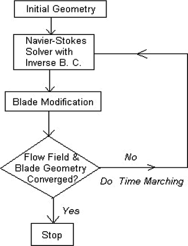
Figure 3. Flow chart for the current inverse method, where the blade modification is an integrated part of the time-marching iteration (BC–boundary conditions).

Figure 4. (a) Rotor 67 efficiency and total pressure ration comparison and (b) Rotor 67 exit spanwise profile of total pressure and total temperature comparison. INV3D vs. test data.
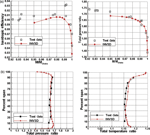
Figure 4. (a) Rotor 67 efficiency and total pressure ration comparison and (b) Rotor 67 exit spanwise profile of total pressure and total temperature comparison. INV3D vs. test data.

Figure 5. Boundary condition on the blade surfaces.

Figure 5. Boundary condition on the blade surfaces.

Figure 6. Numerical instability in camber generation when tip clearance is present. The circles represent the camber wrap angle calculated from the direct integration of camber control equation (Equation Equation13).

Figure 6. Numerical instability in camber generation when tip clearance is present. The circles represent the camber wrap angle calculated from the direct integration of camber control equation (Equation Equation13(13) ).
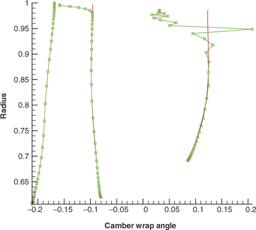
Figure 7. Camber surface generation scheme.

Figure 7. Camber surface generation scheme.

Figure 8. Blade geometry at (a) hub, (b) midspan and (c) tip. Solid line: target blade; Dash line: initial blade; Circle: blade produced by inverse method.
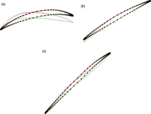
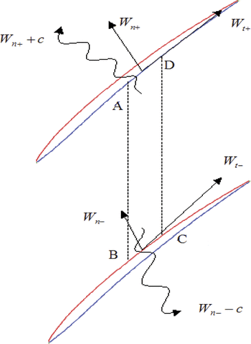
Figure 8. Blade geometry at (a) hub, (b) midspan and (c) tip. Solid line: target blade; Dash line: initial blade; Circle: blade produced by inverse method.
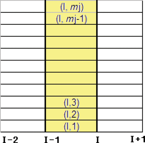
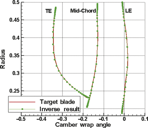
Figure 9. Camber wrap angle resulted from inverse calculation.

Figure 9. Camber wrap angle resulted from inverse calculation.

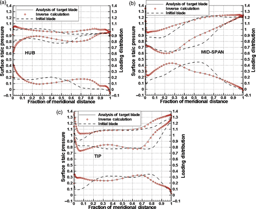
Figure 10. Static pressure and loading distribution at (a) hub, (b) midspan and (c) tip.

Figure 10. Static pressure and loading distribution at (a) hub, (b) midspan and (c) tip.

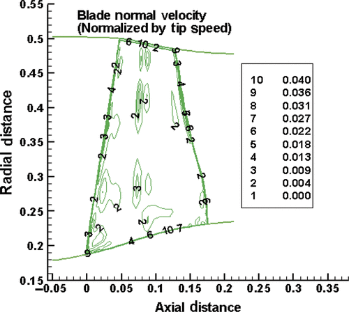
Figure 11. Normal velocity on the blade suction surface.

Figure 11. Normal velocity on the blade suction surface.

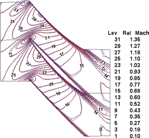
Figure 12. Comparison of Mach number contour at the blade mid-span for analysis and inverse methods.

Figure 12. Comparison of Mach number contour at the blade mid-span for analysis and inverse methods.

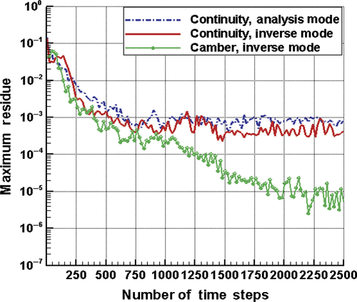
Figure 13. Convergence history of analysis and inverse run.

Figure 13. Convergence history of analysis and inverse run.

Reprints and Corporate Permissions

Please note: Selecting permissions does not provide access to the full text of the article, please see our help page How do I view content?

To request a reprint or corporate permissions for this article, please click on the relevant link below:

Academic Permissions

Please note: Selecting permissions does not provide access to the full text of the article, please see our help page How do I view content?

Obtain permissions instantly via Rightslink by clicking on the button below:

If you are unable to obtain permissions via Rightslink, please complete and submit this Permissions form. For more information, please visit our Permissions help page.