579
Views
14
CrossRef citations to date
0
Altmetric
Original Articles

Optimization of thick rubber part curing cycles

, , &
Pages 313-340 | Received 08 Sep 2008, Accepted 22 Dec 2009, Published online: 18 Mar 2010

Figures & data

Figure 1. Schematic representation of a mould section.

Figure 1. Schematic representation of a mould section.

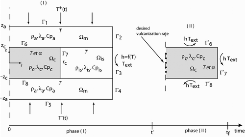
Figure 2. Schematic diagram of the direct problem geometry.

Figure 2. Schematic diagram of the direct problem geometry.

Table 1. Thermophysical properties of the mould and part constituents.

Table 2. Kinetics parameters for THERMEL1 natural rubber.

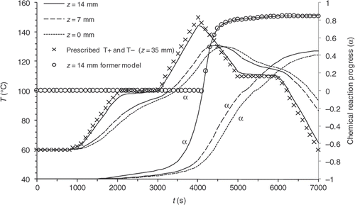
Figure 3. Example 1, cooling inside the mould – – Temperatures and vulcanization rate computed at different points of the part.
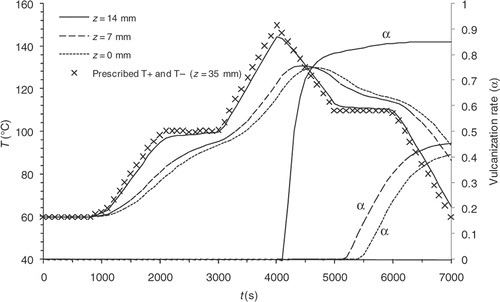
Figure 3. Example 1, cooling inside the mould – – Temperatures and vulcanization rate computed at different points of the part.

Table 3. Discretization of the prescribed temperatures.

Figure 4. Experimental and theoretical temperature values achieved in different points of the moulded part during a moulding cycle.
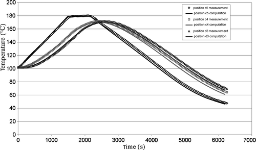
Figure 4. Experimental and theoretical temperature values achieved in different points of the moulded part during a moulding cycle.

Figure 5. Comparison between the vulcanization front position obtained experimentally (a) and calculated (b).
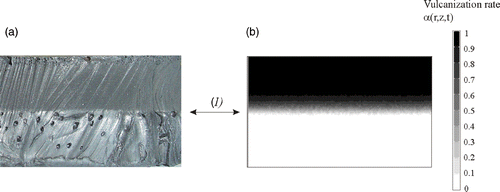
Figure 5. Comparison between the vulcanization front position obtained experimentally (a) and calculated (b).

Figure 6. Example 2, 1000 s cooling outside the mould: , – temperatures and vulcanization rate computed at different points of the part.
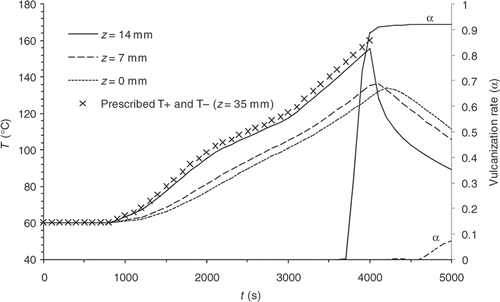
Figure 6. Example 2, 1000 s cooling outside the mould: , – temperatures and vulcanization rate computed at different points of the part.

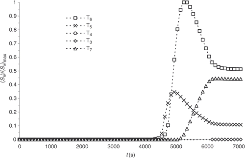
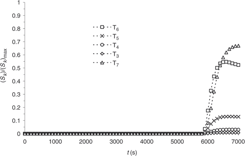
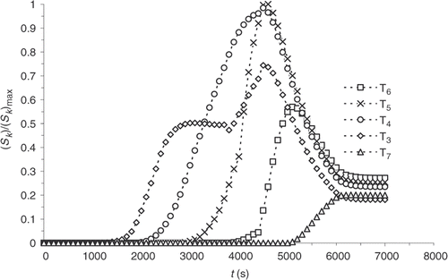
Figure 7. Sensitivity evolution at the surface of the part.

Figure 7. Sensitivity evolution at the surface of the part.

Figure 8. Sensitivity evolution at the centre of the part.

Figure 8. Sensitivity evolution at the centre of the part.

Figure 9. Chemical reaction progress with the new model.

Figure 9. Chemical reaction progress with the new model.

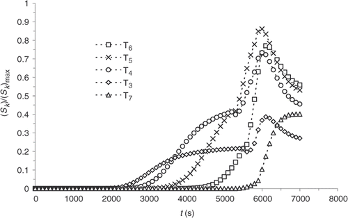
Figure 10. Sensitivity evolution at the surface of the part with the new model.

Figure 10. Sensitivity evolution at the surface of the part with the new model.

Figure 11. Sensitivity evolution at the centre of the part with the new model.

Figure 11. Sensitivity evolution at the centre of the part with the new model.

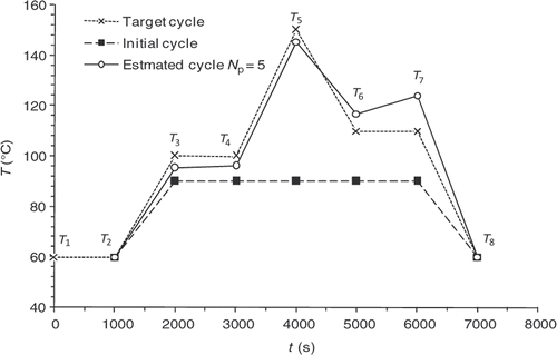
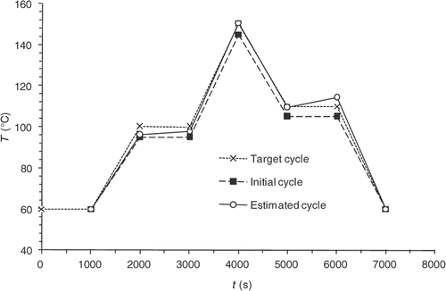
Figure 12. Optimization Example 1 – heating and cooling inside the mould. . fixed at . .

Figure 12. Optimization Example 1 – heating and cooling inside the mould. . fixed at . .

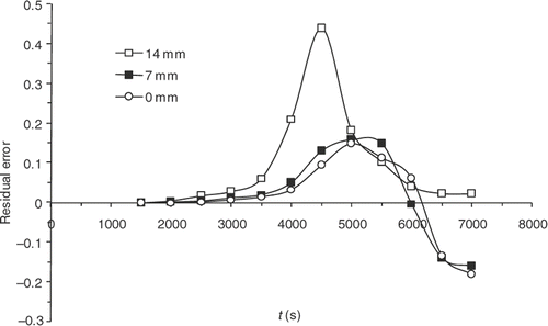
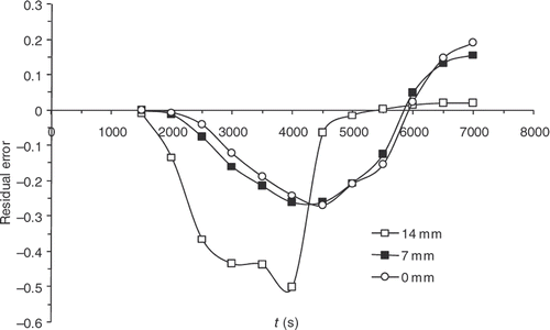
Figure 13. Example 1 – Residual error versus time – heating and cooling inside the mould.

Figure 13. Example 1 – Residual error versus time – heating and cooling inside the mould.

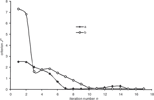
Figure 14. Least squares criterion versus iteration numbers – a: Example 1 (Nt = 12); b: effect of the initial cycle; c: Example 1 (Nt = 1).
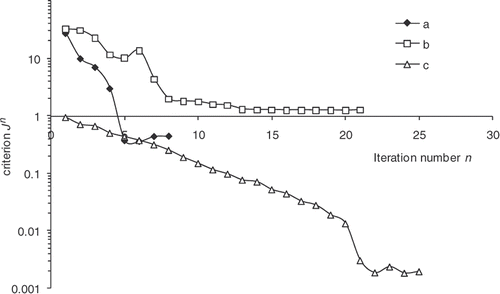
Figure 14. Least squares criterion versus iteration numbers – a: Example 1 (Nt = 12); b: effect of the initial cycle; c: Example 1 (Nt = 1).

Figure 15. Influence of the initial cycle.

Figure 15. Influence of the initial cycle.

Figure 16. Progress residual error versus time.

Figure 16. Progress residual error versus time.

Figure 17. Example 1 with Nt = 1.

Figure 17. Example 1 with Nt = 1.

Figure 18. Cooling within the mould – , fixed.

Figure 18. Cooling within the mould – , fixed.

Figure 19. Least-squares criterion – a: cooling inside the mould; b: cooling outside the mould.

Figure 19. Least-squares criterion – a: cooling inside the mould; b: cooling outside the mould.

Figure 20. Vulcanization rate within the part thickness – a: desired vulcanization rate; b: vulcanization rate obtained with estimated cycle; c: vulcanization rate obtained with initial cycle.
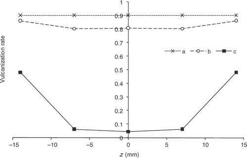
Figure 20. Vulcanization rate within the part thickness – a: desired vulcanization rate; b: vulcanization rate obtained with estimated cycle; c: vulcanization rate obtained with initial cycle.

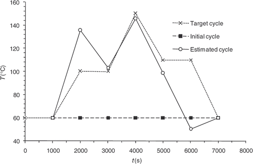
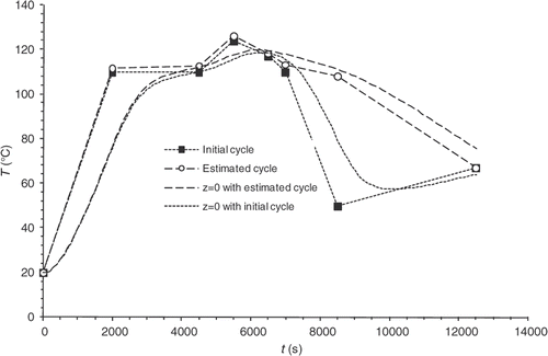
Figure 21. Estimated cycle – cooling outside the mould between 4000 and 5000 s –, , , fixed.

Figure 21. Estimated cycle – cooling outside the mould between 4000 and 5000 s –, , , fixed.

Figure 22. Chemical reaction progress within the part thickness. Desired vulcanization rate: 0.9 – a: α obtained at the end of heating in the mould with the estimated cycle, b: α obtained at the end of heating in the mould with the initial cycle, c: α obtained at the end of cooling outside the mould with the estimated cycle, d: α obtained at the end of cooling outside the mould with the initial cycle.
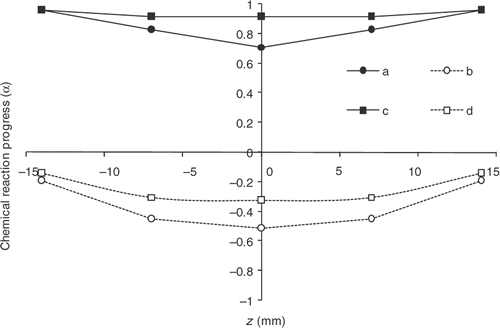
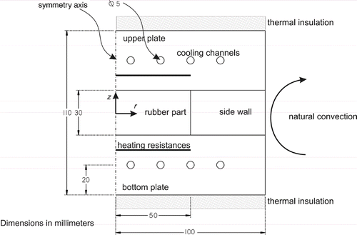
Figure 22. Chemical reaction progress within the part thickness. Desired vulcanization rate: 0.9 – a: α obtained at the end of heating in the mould with the estimated cycle, b: α obtained at the end of heating in the mould with the initial cycle, c: α obtained at the end of cooling outside the mould with the estimated cycle, d: α obtained at the end of cooling outside the mould with the initial cycle.
Reprints and Corporate Permissions

Please note: Selecting permissions does not provide access to the full text of the article, please see our help page How do I view content?

To request a reprint or corporate permissions for this article, please click on the relevant link below:

Academic Permissions

Please note: Selecting permissions does not provide access to the full text of the article, please see our help page How do I view content?

Obtain permissions instantly via Rightslink by clicking on the button below:

If you are unable to obtain permissions via Rightslink, please complete and submit this Permissions form. For more information, please visit our Permissions help page.