512
Views
0
CrossRef citations to date
0
Altmetric
Special Issue Papers

Tool shape design in V-bending and channel forming processes by inverse analysis of springback

, &
Pages 465-480 | Received 02 Jan 2010, Accepted 03 Jan 2010, Published online: 05 Mar 2010

Figures & data

Figure 1. Algorithm of inverse springback analysis for compensating springback error in V-bending process.
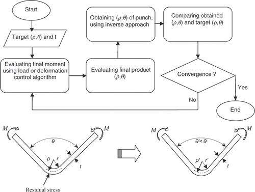
Figure 1. Algorithm of inverse springback analysis for compensating springback error in V-bending process.

Figure 2. Algorithm of inverse springback analysis by FEM.

Figure 2. Algorithm of inverse springback analysis by FEM.

Figure 3. Algorithm of compensating springback error by inverse FE modelling.

Figure 3. Algorithm of compensating springback error by inverse FE modelling.

Figure 4. Stress–strain curve of applied sheets: (a) St-12 (thickness = 1 mm) and (b) annealed CK45 (thickness = 1 mm).
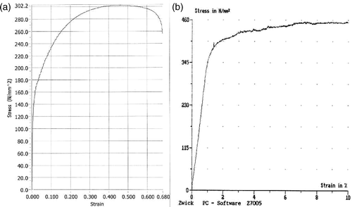
Figure 4. Stress–strain curve of applied sheets: (a) St-12 (thickness = 1 mm) and (b) annealed CK45 (thickness = 1 mm).

Figure 5. Die setting for (a) initial (90° bending) and (b) optimised (90° bending) V-bending process (dimensions are in millimeter).
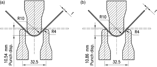
Figure 5. Die setting for (a) initial (90° bending) and (b) optimised (90° bending) V-bending process (dimensions are in millimeter).

Figure 6. Convergence diagram for V-bending process: (a) inverse algorithm and (b) forward algorithm.
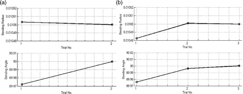
Figure 6. Convergence diagram for V-bending process: (a) inverse algorithm and (b) forward algorithm.

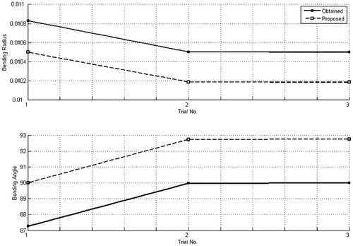
Figure 7. Proposed and obtained bending angle and radius by inverse approach.

Figure 7. Proposed and obtained bending angle and radius by inverse approach.

Figure 8. Deformed shape at the end of loading and unloading steps: (a) forward analysis and (b) inverse analysis.
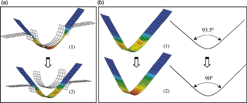
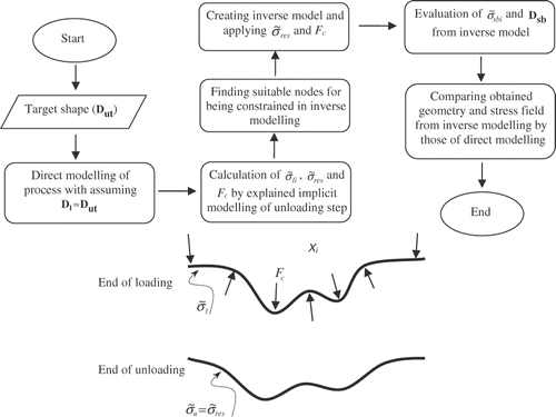
Figure 8. Deformed shape at the end of loading and unloading steps: (a) forward analysis and (b) inverse analysis.
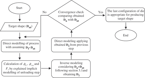
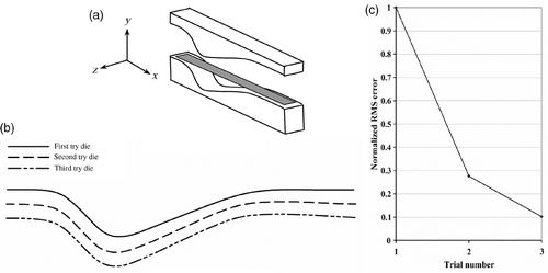
Figure 9. Asymmetric bending results: (a) asymmetric bending die, (b) die profiles in each try and (c) convergence diagram.

Figure 9. Asymmetric bending results: (a) asymmetric bending die, (b) die profiles in each try and (c) convergence diagram.

Figure 10. Comparison of the obtained product shape with the target shape.

Figure 10. Comparison of the obtained product shape with the target shape.

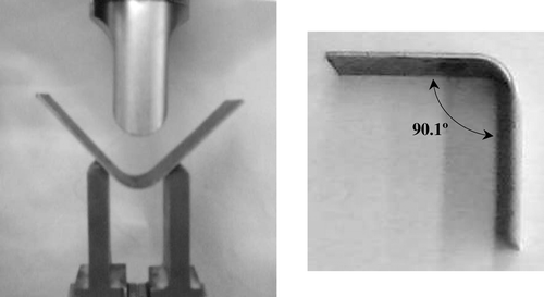
Figure 11. V-bending test and the obtained product.

Figure 11. V-bending test and the obtained product.

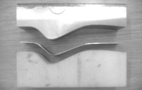
Figure 12. Asymmetric bending test.

Figure 12. Asymmetric bending test.

Figure 13. Comparison of the experiment product with the target shape.

Figure 13. Comparison of the experiment product with the target shape.

Reprints and Corporate Permissions

Please note: Selecting permissions does not provide access to the full text of the article, please see our help page How do I view content?

To request a reprint or corporate permissions for this article, please click on the relevant link below:

Academic Permissions

Please note: Selecting permissions does not provide access to the full text of the article, please see our help page How do I view content?

Obtain permissions instantly via Rightslink by clicking on the button below:

If you are unable to obtain permissions via Rightslink, please complete and submit this Permissions form. For more information, please visit our Permissions help page.