208
Views
2
CrossRef citations to date
0
Altmetric
Original Articles

Detection of anomalies inside hollow metal cylindrical structures

, , &
Pages 613-634 | Received 09 Feb 2009, Accepted 01 Feb 2010, Published online: 19 Mar 2010

Figures & data

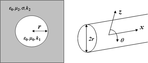
Figure 1. Metal cylindrical hollow structure.

Figure 1. Metal cylindrical hollow structure.

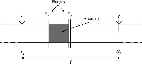
Figure 2. Section of a metal cylindrical hollow structure.

Figure 2. Section of a metal cylindrical hollow structure.

Figure 3. System geometry and cylindrical reference system (z, θ, x).

Figure 3. System geometry and cylindrical reference system (z, θ, x).

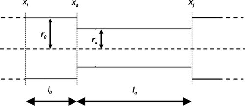
Figure 4. Circular anomaly as a constant radial reduction.

Figure 4. Circular anomaly as a constant radial reduction.

Figure 5. Lookup-table with different curves βi(f) for different pairs (la, rap)i. Note: la varies from 0 to 12 m with steps of 1 m; rap varies from 0% to 10% with steps of 1%. The curves are not equally spaced and the mapping is strongly non-linear.
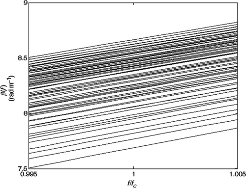
Figure 5. Lookup-table with different curves βi(f) for different pairs (la, rap)i. Note: la varies from 0 to 12 m with steps of 1 m; rap varies from 0% to 10% with steps of 1%. The curves are not equally spaced and the mapping is strongly non-linear.

Figure 6. βi(f) curves as a function of normalized frequency, for some (la, ra)i pairs. Section length ls = 12 m.
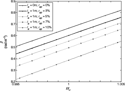
Figure 6. βi(f) curves as a function of normalized frequency, for some (la, ra)i pairs. Section length ls = 12 m.

Figure 7. βi(f) curves as a function of normalized frequency, for some (la, ra)i pairs. Section length ls = 24 m.
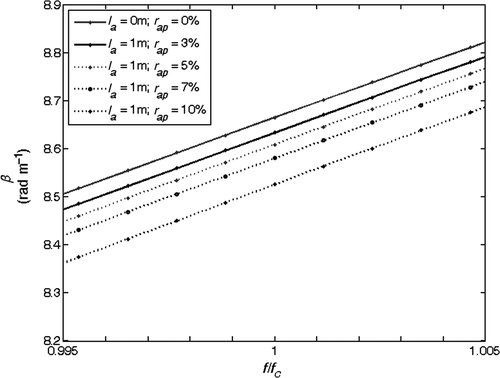
Figure 7. βi(f) curves as a function of normalized frequency, for some (la, ra)i pairs. Section length ls = 24 m.

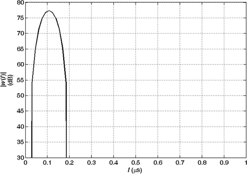
Figure 8. Absolute value of the transmitted waveform (after demodulation).

Figure 8. Absolute value of the transmitted waveform (after demodulation).

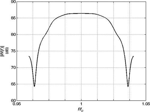
Figure 9. Spectrum amplitude of the transmitted signal shown in .

Figure 9. Spectrum amplitude of the transmitted signal shown in Figure 8.

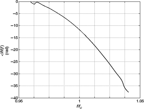
Figure 10. Spectrum phase of the transmitted signal shown in .

Figure 10. Spectrum phase of the transmitted signal shown in Figure 8.

Figure 11. Absolute value of the echoes from the joints at coordinates xi and xj: la = 0 m, rap = 0%.
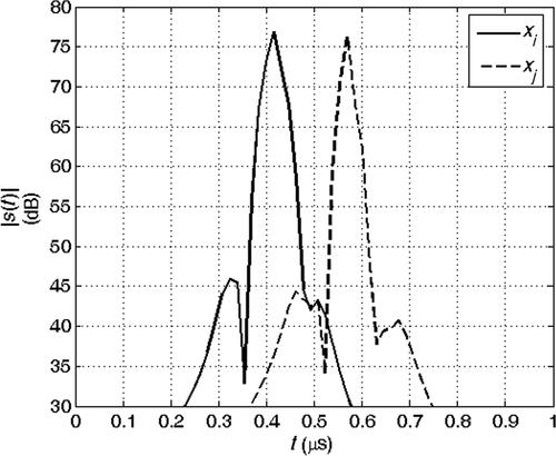
Figure 11. Absolute value of the echoes from the joints at coordinates xi and xj: la = 0 m, rap = 0%.

Figure 12. Absolute value of the echoes from the joints at coordinates xi and xj: la = 2 m, rap = 3%.
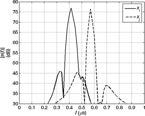
Figure 12. Absolute value of the echoes from the joints at coordinates xi and xj: la = 2 m, rap = 3%.

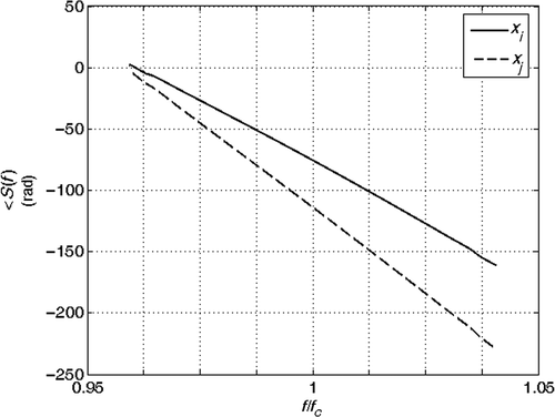
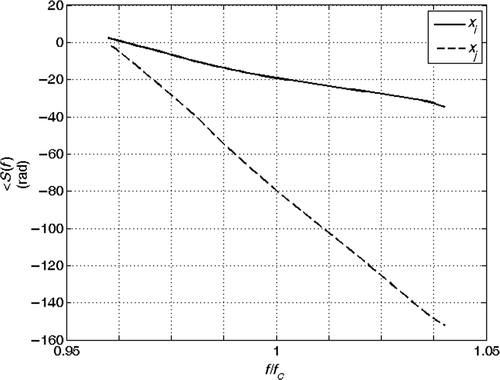
Figure 13. Spectra phase of the signals in .

Figure 13. Spectra phase of the signals in Figure 11.

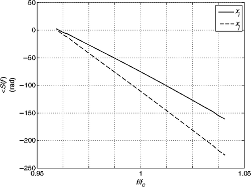
Figure 14. Spectra phase of the signals in .

Figure 14. Spectra phase of the signals in Figure 12.

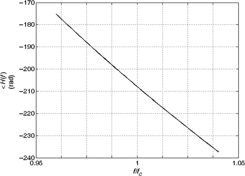
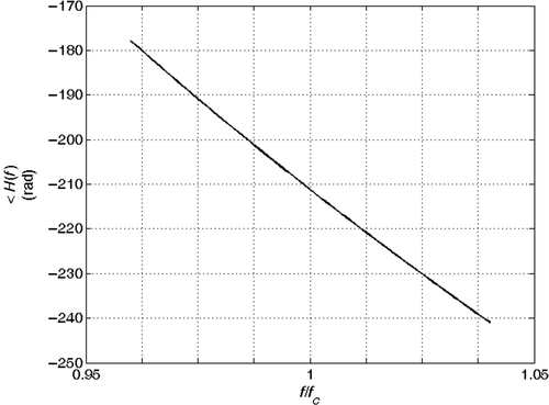
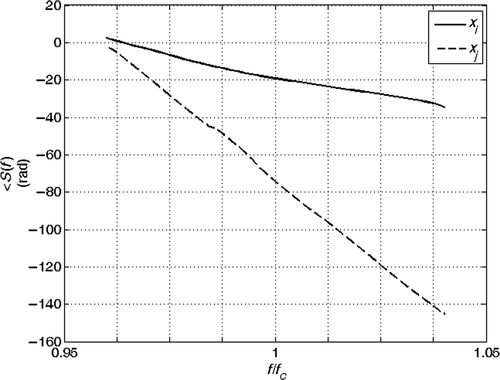
Figure 15. Phase of the spectra ratio of the joints at coordinates xi and xj: la = 0 m, rap = 0%.

Figure 15. Phase of the spectra ratio of the joints at coordinates xi and xj: la = 0 m, rap = 0%.

Figure 16. Phase of the spectra ratio of the joints at coordinates xi and xj: la = 2 m, rap = 3%.

Figure 16. Phase of the spectra ratio of the joints at coordinates xi and xj: la = 2 m, rap = 3%.

Figure 17. Mean value of the inverted anomaly length versus SNR. Exact solution: la = 2 m and rap = 3%.
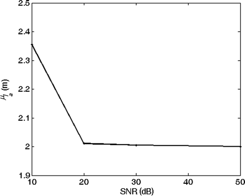
Figure 17. Mean value of the inverted anomaly length versus SNR. Exact solution: la = 2 m and rap = 3%.

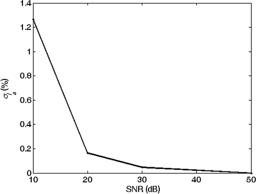
Figure 18. SD of the inverted anomaly length versus SNR. Exact solution: la = 2 m and rap = 3%.

Figure 18. SD of the inverted anomaly length versus SNR. Exact solution: la = 2 m and rap = 3%.

Figure 19. Mean value of the inverted percentage radius reduction versus SNR. Exact solution: la = 2 m and rap = 3%.
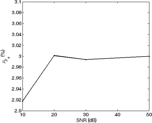
Figure 19. Mean value of the inverted percentage radius reduction versus SNR. Exact solution: la = 2 m and rap = 3%.

Figure 20. SD of the inverted percentage radius reduction versus SNR. Exact solution: la = 2 m and rap = 3%.
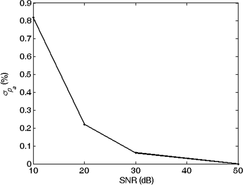
Figure 20. SD of the inverted percentage radius reduction versus SNR. Exact solution: la = 2 m and rap = 3%.

Table 1. Inverted parameters–synthetic data: regular (a) and deformed (b) elements.

Figure 21. Experimental setup for the detection of the circular anomaly.

Figure 21. Experimental setup for the detection of the circular anomaly.

Figure 22. Real data for a regular section. The arrows indicate the starting time of the echoes from the joints.
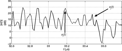
Figure 22. Real data for a regular section. The arrows indicate the starting time of the echoes from the joints.

Figure 23. Real data for a deformed section. The arrows indicate the starting time of the echoes from the joints.
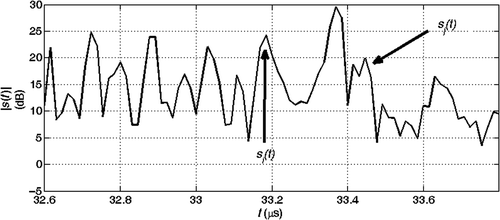
Figure 23. Real data for a deformed section. The arrows indicate the starting time of the echoes from the joints.

Figure 24. Absolute value of the echoes from the joints at coordinates xi = 84 m and xj = 108 m: real data with regular section.
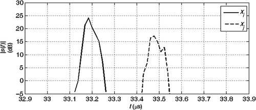
Figure 24. Absolute value of the echoes from the joints at coordinates xi = 84 m and xj = 108 m: real data with regular section.

Figure 25. Absolute value of the echoes from the joints at coordinates xi = 84 m and xj = 108 m: real data with deformed section.
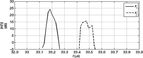
Figure 25. Absolute value of the echoes from the joints at coordinates xi = 84 m and xj = 108 m: real data with deformed section.

Figure 26. Spectra phase of the signals in .

Figure 26. Spectra phase of the signals in Figure 24.

Figure 27. Spectra phase of the signals in .

Figure 27. Spectra phase of the signals in Figure 25.

Figure 28. Phase of the spectra ratio of the joints echoes at xi = 84 m and xj = 108 m: real data with regular section.
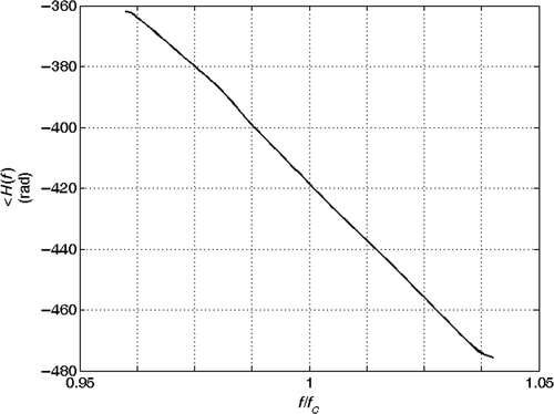
Figure 28. Phase of the spectra ratio of the joints echoes at xi = 84 m and xj = 108 m: real data with regular section.

Figure 29. Phase of the spectra ratio of the joints echoes at xi = 84 m and xj = 108 m: real data with deformed section.
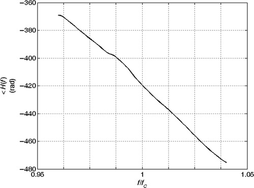
Figure 29. Phase of the spectra ratio of the joints echoes at xi = 84 m and xj = 108 m: real data with deformed section.

Table 2. Inverted parameters–real data: regular (a) and deformed (b) elements.

Reprints and Corporate Permissions

Please note: Selecting permissions does not provide access to the full text of the article, please see our help page How do I view content?

To request a reprint or corporate permissions for this article, please click on the relevant link below:

Academic Permissions

Please note: Selecting permissions does not provide access to the full text of the article, please see our help page How do I view content?

Obtain permissions instantly via Rightslink by clicking on the button below:

If you are unable to obtain permissions via Rightslink, please complete and submit this Permissions form. For more information, please visit our Permissions help page.