556
Views
10
CrossRef citations to date
0
Altmetric
Original Articles

Modelling mechanical interfaces experiencing micro-slip/slap

, &
Pages 751-764 | Received 05 Feb 2010, Accepted 06 Oct 2010, Published online: 06 Feb 2011

Figures & data

Figure 1. The structure including a contact interface and its corresponding FE model.

Figure 1. The structure including a contact interface and its corresponding FE model.

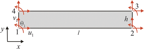
Figure 2. The 2D thin-layer element.

Figure 2. The 2D thin-layer element.

Figure 3. Test structure with an interface area of 50 × 25.4 mm2, structure geometrical dimensions and the location of applied force and measurements.
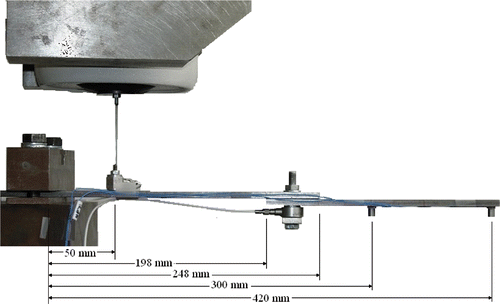
Figure 3. Test structure with an interface area of 50 × 25.4 mm2, structure geometrical dimensions and the location of applied force and measurements.

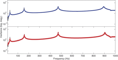
Figure 4. Linear FRFs: pre-loads of 120 N (▪) and 540 N (•).

Figure 4. Linear FRFs: pre-loads of 120 N (▪) and 540 N (•).

Table 1. Experimental and updated natural frequencies at different pre-loads.

Figure 5. Nonlinear FRFs at different excitation levels: F = 1.5 N (•), F = 3 N (▾) and F = 6 N (♦); pre-loads of 540 N (right) and 120 N (left).
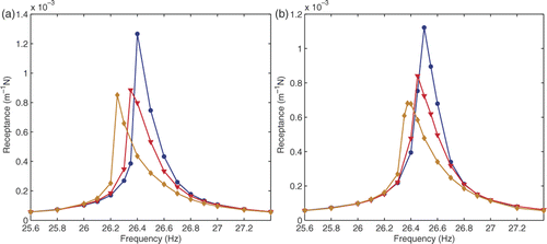
Figure 5. Nonlinear FRFs at different excitation levels: F = 1.5 N (•), F = 3 N (▾) and F = 6 N (♦); pre-loads of 540 N (right) and 120 N (left).

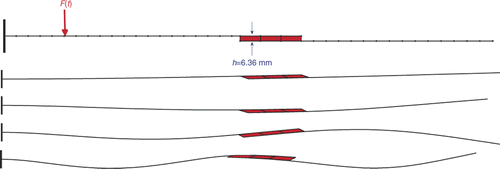
Figure 6. FE mesh and the mode shapes of the updated FE model.

Figure 6. FE mesh and the mode shapes of the updated FE model.

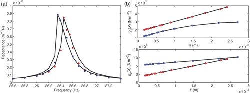
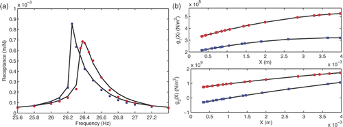
Figure 7. Experimental (lines) and predicted (marks) FRFs (left), updated functions g1(X) and g2(X) (right); at pre-loads of 120 N (▪) and 540 N (•).
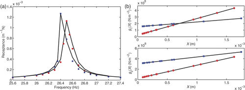
Figure 7. Experimental (lines) and predicted (marks) FRFs (left), updated functions g1(X) and g2(X) (right); at pre-loads of 120 N (▪) and 540 N (•).

Figure 8. Changes in objective function (left) and updating parameters (right) at a pre-load of 120 N.
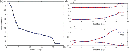
Figure 8. Changes in objective function (left) and updating parameters (right) at a pre-load of 120 N.

Figure 9. Experimental (lines) and predicted (marks) FRFs (left), updated functions g1(X) and g2(X) (right); pre-loads of 120 N (▪) and 540 N (•).

Figure 9. Experimental (lines) and predicted (marks) FRFs (left), updated functions g1(X) and g2(X) (right); pre-loads of 120 N (▪) and 540 N (•).

Figure 10. Experimental (lines) and predicted (marks) FRFs (left), updated functions g1(X) and g2(X) (right); pre-loads of 120 N (▪) and 540 N (•).

Figure 10. Experimental (lines) and predicted (marks) FRFs (left), updated functions g1(X) and g2(X) (right); pre-loads of 120 N (▪) and 540 N (•).

Reprints and Corporate Permissions

Please note: Selecting permissions does not provide access to the full text of the article, please see our help page How do I view content?

To request a reprint or corporate permissions for this article, please click on the relevant link below:

Academic Permissions

Please note: Selecting permissions does not provide access to the full text of the article, please see our help page How do I view content?

Obtain permissions instantly via Rightslink by clicking on the button below:

If you are unable to obtain permissions via Rightslink, please complete and submit this Permissions form. For more information, please visit our Permissions help page.