246
Views
2
CrossRef citations to date
0
Altmetric
Original Articles

The inverse determination of the thermal contact resistance components of unidirectionally reinforced composite

&
Pages 283-297 | Received 04 Sep 2011, Accepted 10 May 2012, Published online: 26 Jun 2012

Figures & data

Figure 1. A unidirectional reinforced fibrous composite with fibre arrangement according to a square array for the imperfect thermal contact between fibre and matrix: (a) general view, (b) formulation of a nondimensional boundary value problem in a repeated element.
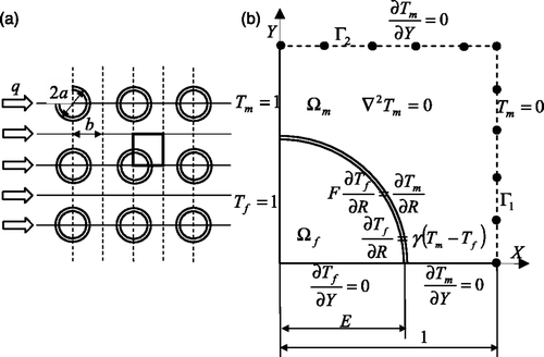
Figure 1. A unidirectional reinforced fibrous composite with fibre arrangement according to a square array for the imperfect thermal contact between fibre and matrix: (a) general view, (b) formulation of a nondimensional boundary value problem in a repeated element.

Figure 2. The effective thermal conductivity as a function of radius of fibres in the matrix for different values of the ratio of thermal conductivity fibres to the matrix, F, and for different values of resistance number, γ.
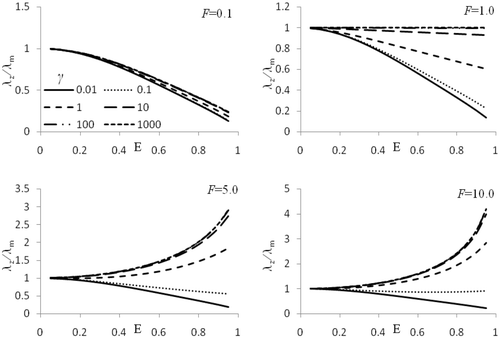
Figure 2. The effective thermal conductivity as a function of radius of fibres in the matrix for different values of the ratio of thermal conductivity fibres to the matrix, F, and for different values of resistance number, γ.

Table 1. The value of resistance number γ for E = 0.7, for the different values of F for known temperature in M3 points in the matrix and for known λzm.

Table 2. The value of resistance number γ for E = 0.7, for the different values of F for known temperature in M3 points on the upper boundary and for known λzm.

Table 3. The value of resistance number γ for E = 0.7, for the different values of F for known temperature in N3 = 10 points in the matrix and for known λzm for disturbed data ΔT = 0.1%.

Table 4. The value of resistance number γ for E = 0.7, for the different values of F for known temperature in N3 = 10 points on the upper boundary and for known λzm for disturbed data ΔT = 0.1%.

Table 5. The impact of the number of collocation points on the value of the resistance number and the maximum error of fulfilling the boundary conditions at control points.

Table 6. Convergence of the Levenberg–Marquardt method for the four test examples.

Reprints and Corporate Permissions

Please note: Selecting permissions does not provide access to the full text of the article, please see our help page How do I view content?

To request a reprint or corporate permissions for this article, please click on the relevant link below:

Academic Permissions

Please note: Selecting permissions does not provide access to the full text of the article, please see our help page How do I view content?

Obtain permissions instantly via Rightslink by clicking on the button below:

If you are unable to obtain permissions via Rightslink, please complete and submit this Permissions form. For more information, please visit our Permissions help page.