Figures & data
Figure 1. First three of the nine indentation test patterns for two-dimensional test cases.
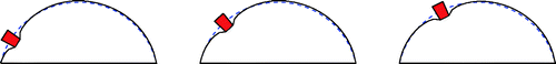
Figure 2. Finite element meshes used to represent individuals (a) Two-dimensional mesh and (b) Three-dimensional mesh.
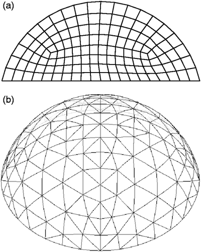
Figure 3. Chromosome used to encode material property information for each individual. (Eh is healthy modulus, Ec is cancerous modulus.)
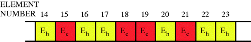
Figure 4. Model problem geometry for two-dimensional test cases.
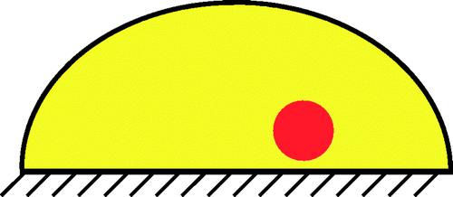
Figure 5. Finite element mesh showing ‘clumps’ of potential tumour elements.
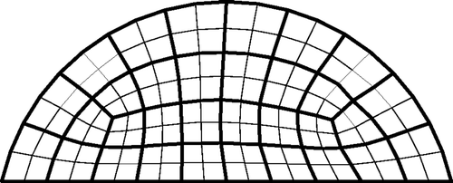
Figure 6. Challenging test case for 20 trials with SNR = 23 dB. Bold/green/grey lines show the location of the test tumours, and the numbers in the elements indicate how many times the algorithm identified that clump of elements as a tumour. For every trial at least eight elements were identified as cancerous.
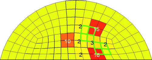
Figure 7. Results for eight different test cases with SNR = 23 dB and 20 trials. Bold/green/grey lines show the location of the test tumours, and the numbers in the elements indicate how many times the algorithm identified that clump of elements as a tumour. For every trial containing a test tumour at least four elements were identified as cancerous.
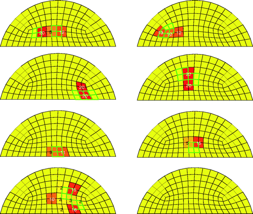
Figure 8. Typical result (Test A) at SNR = 23 dB. The true tumour crosses two clumps, adjacent to the chest wall and tissue centerline. True tumour is shown in bold/green/grey and prediction is red/black. True tumour volume is 0.96 cm3. (a) Bottom view and (b) Side view.
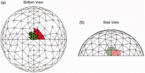
Figure 9. Result for Test B (20/20 trials) at SNR = 23 dB. The true tumour crosses eight clumps. True tumour is shown in bold/green/grey and prediction is red/black. True tumour volume is 1.02 cm3. (a) Bottom view and (b) Side view.
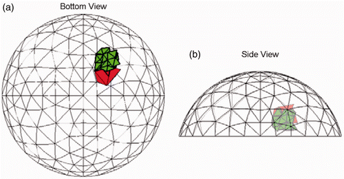
Figure 10. Result for Test C (20/20trials) at SNR = 23 dB. The true tumour crosses eight clumps. True tumour is shown in bold/green/grey and prediction is red/black. True tumour volume is 1.13 cm3. (a) Bottom view and (b) Side view.
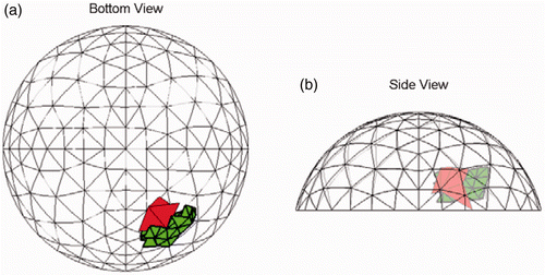
Figure 11. Most common (9/20 trials) result for Test D at SNR = 23 dB. The true tumour crosses four clumps. True tumour is shown in bold/green/grey and prediction is red/black. True tumour volume is 0.99 cm3. (a) Bottom view and (b) Side view.
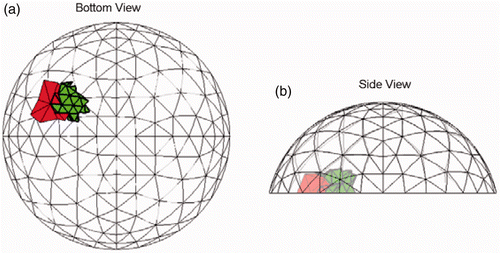
Figure 12. Most common (16/20 trials) result for Test E at SNR = 23 dB. Each of the sites in the true tumour crosses eight clumps. True tumour is shown in bold/green/grey and prediction is red/black. True tumour volume is 1.92 cm3, divided roughly equally between the two sites. (a) Bottom view and (b) Side view.
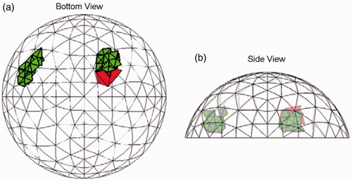
Figure 13. Result for Test F (20/20 trials) at SNR = 23 dB. The true tumour crosses eight clumps. True tumour is shown in bold/green/grey and prediction is red/black. True tumour volume is 2.07 cm3. (a) Bottom view and (b) Side view.
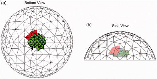
Figure 14. Result for Test G (20/20 trials) at SNR = 23 dB. The true tumour crosses twenty-two clumps. True tumour is shown in bold/green/grey and prediction is red/black. True tumour volume is 2.10 cm3. (a) Bottom view and (b) Side view.
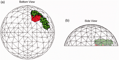
Figure A1. Nine indentation test patterns for three-dimensional test cases.
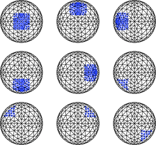
Table 1. Parameter settings for 2D and 3D GA.
Figure B1. Mating parents to create children.
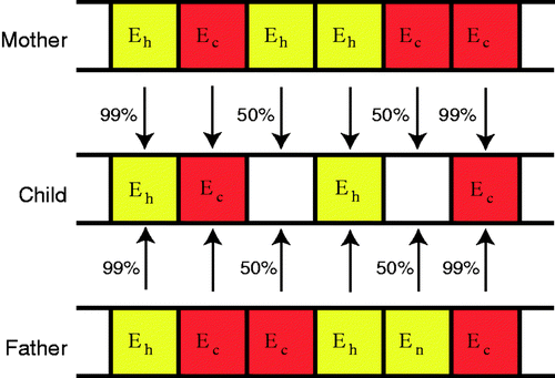
Figure C1. Applying the nodal surface constraints.
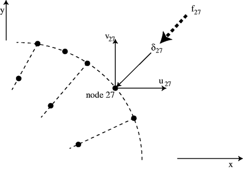
Figure D1. Finer mesh used to create measured data for original mesh in two dimensions. (a) Original 2D mesh and (b) Finer 2D mesh.
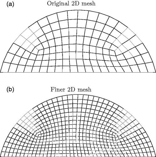
Figure D2. Finer mesh used to create measured data for original mesh in three dimensions. (a) Original 2D mesh and (b) Finer 2D mesh.
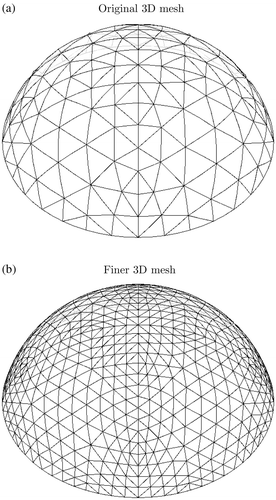
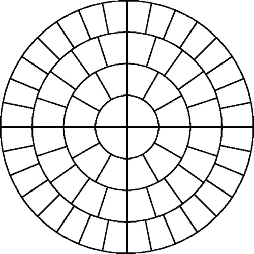
Figure E1. Radial and circumferential boundaries for three-dimensional clumps.