Figures & data
Fig. 1 The Mainz tomograph.
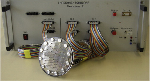
Fig. 2 The sensing head.
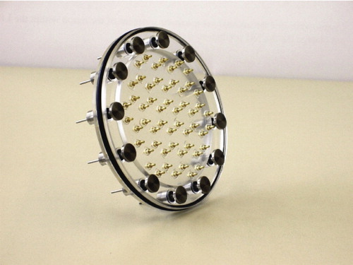
Fig. 3 The data acquisition device.
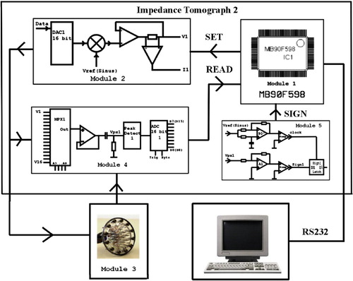
Fig. 4 Experimental setup.
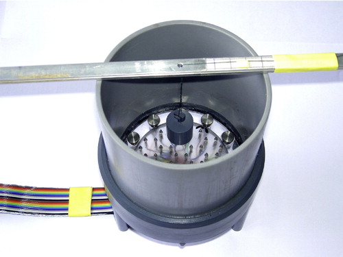
Fig. 5 Layout of the electrode array of the Mainz EIT device. The small circles labelled from 1 to 12 show the outer electrodes for current injection. The position of the 54 inner electrodes for potential measurements are drawn as thick points (marked in blue). The network is used as a model of the measurement area. The positions 1, 2 and 3 (marked in red) indicate the places above the sensing head where metallic objects were immersed in conducting liquid for the experimental set-up described in Figure , while the positions 4 and 5 (marked in yellow) indicate the places where an agar phantom was placed.
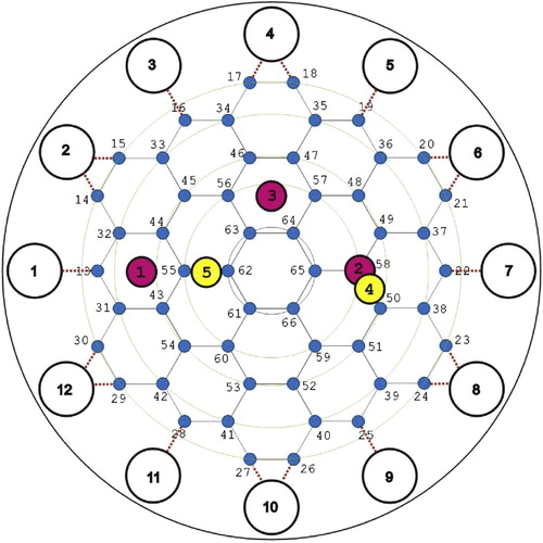
Fig. 6 Conductivity reconstructions from reference data (small tank filled with salt water and no immersed objects) : (a) using the integral equation approach and (b) using the resistor network approach.
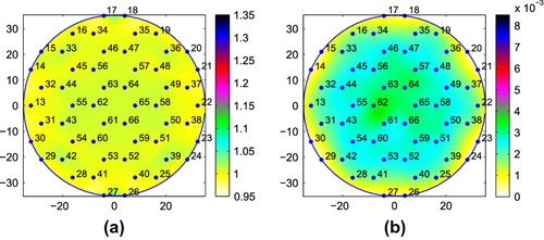
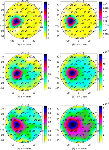
Fig. 7 Conductivity reconstructions for M20 placed at position 1 (small tank): (a), (c) and (e) using the integral equation approach; (b), (d) and (f) using the resistor network approach.
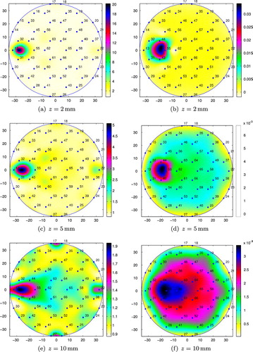
Fig. 8 Conductivity reconstructions for M15 placed at position 1 (small tank): (a), (c), and (e) using the integral equation approach; (b), (d), and (f) using the resistor network approach.
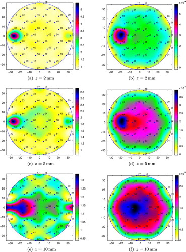
Fig. 9 Conductivity reconstructions for M15 placed at position 2 (small tank): (a), (c), (e) and (g) using the integral equation approach; (b), (d), (f) and (h) using the resistor network approach.
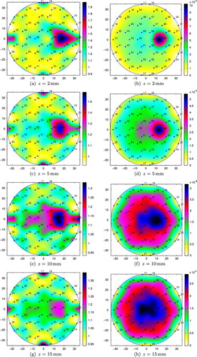
Fig. 10 Conductivity reconstructions for M15 placed at position 3 (small tank): (a), (c) and (e) using the integral equation approach; (b), (d) and (f) using the resistor network approach.
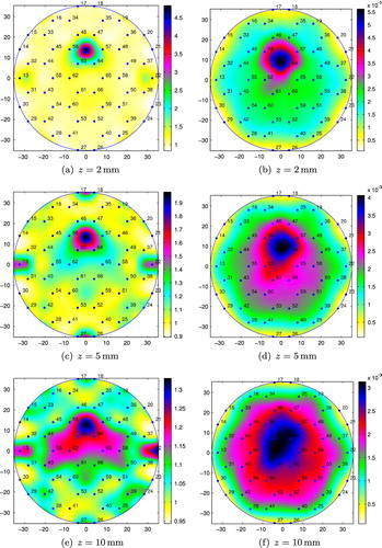
Fig. 11 Conductivity reconstructions for M15 placed at position 3 (large tank): (a), (c) and (e) using the integral equation approach; (b), (d) and (f) using the resistor network approach.
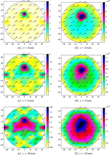
Fig. 12 Conductivity reconstructions for M15 placed at position 1 and M20 placed at position 3 (small tank): (a) and (c) using the integral equation approach; (b) and (d) using the resistor network approach.
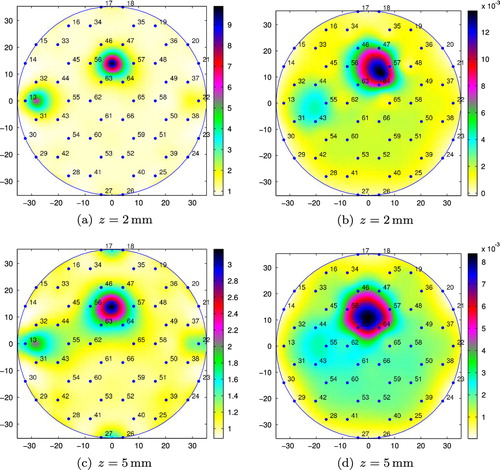
Fig. 13 Conductivity reconstructions for M20 placed at position 1 and M15 placed at position 3 (small tank): (a) and (c) using the integral equation approach; (b) and (d) using the resistor network approach.
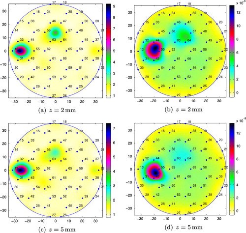
Fig. 14 Conductivity reconstructions for a cubic agar phantom placed at position 4 (small tank): (a), (c) and (e) using the integral equation approach; (b), (d) and (f) using the resistor network approach.
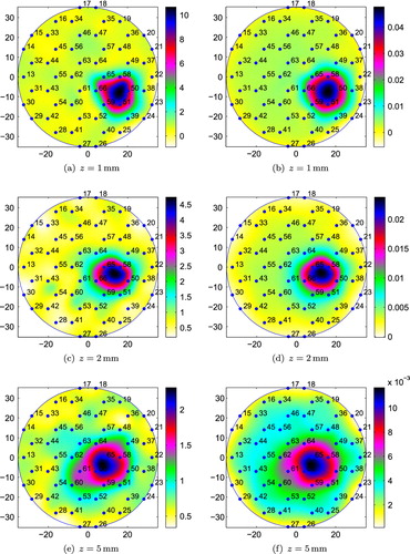
Fig. 15 Conductivity reconstructions for a cubic agar phantom placed at position 5 (small tank): (a), (c) and (e) using the integral equation approach; (b), (d) and (f) using the resistor network approach.