616
Views
22
CrossRef citations to date
0
Altmetric
Articles

Sparse 3D reconstructions in electrical impedance tomography using real data

, , &
Pages 31-44 | Received 09 Jul 2013, Accepted 13 Jul 2013, Published online: 12 Aug 2013

Figures & data

Fig. 1 The sensing head.

Fig. 1 The sensing head.

Fig. 2 Layout of the electrode array of the Mainz EIT device. The small circles labelled from 1 to 12 show the outer electrodes for current injection. The position of the 54 inner electrodes for potential measurements are drawn as thick points. The network is used as a model of the measurement area. The positions 1, 2 and 3 indicate the places above the sensing head where metallic objects were immersed in conducting liquid, while the positions 4 and 5 indicate the places where an agar phantom was placed.
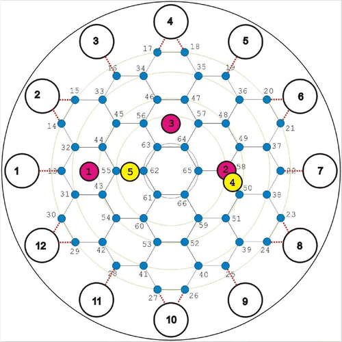
Fig. 2 Layout of the electrode array of the Mainz EIT device. The small circles labelled from 1 to 12 show the outer electrodes for current injection. The position of the 54 inner electrodes for potential measurements are drawn as thick points. The network is used as a model of the measurement area. The positions 1, 2 and 3 indicate the places above the sensing head where metallic objects were immersed in conducting liquid, while the positions 4 and 5 indicate the places where an agar phantom was placed.

Fig. 3 Conductivity reconstructions for the agar phantom placed at position 5 and at different distances below the sensing head: (a) and (c) 2 mm; (b) and (d) 5 mm. (a) and (b): cross-sections of conductivity reconstructions; (c) and (d): three-dimensional views of the conductivity reconstructions.
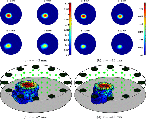
Fig. 3 Conductivity reconstructions for the agar phantom placed at position 5 and at different distances below the sensing head: (a) and (c) 2 mm; (b) and (d) 5 mm. (a) and (b): cross-sections of conductivity reconstructions; (c) and (d): three-dimensional views of the conductivity reconstructions.

Fig. 4 Cross-sections of conductivity reconstruction for M15 at position 1 and M20 at position 2. The inclusion is (a) 2 mm and (b) 5 mm below the sensing head.
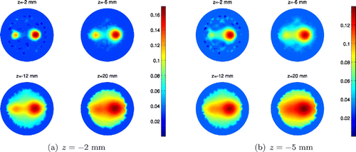
Fig. 4 Cross-sections of conductivity reconstruction for M15 at position 1 and M20 at position 2. The inclusion is (a) 2 mm and (b) 5 mm below the sensing head.

Fig. 5 Cross-sections of conductivity reconstruction for M15 at position 2 and M20 at position 1. The inclusion is (a) 2 mm and (b) 5 mm below the sensing head.
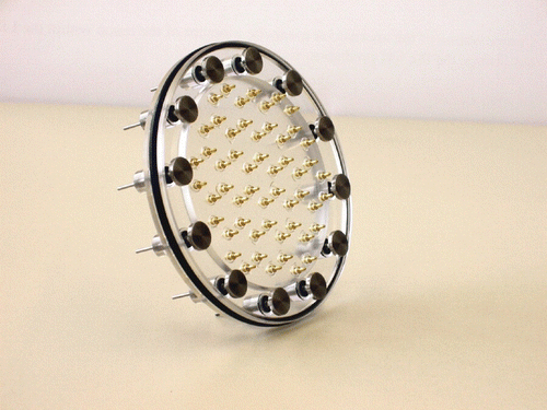
Fig. 5 Cross-sections of conductivity reconstruction for M15 at position 2 and M20 at position 1. The inclusion is (a) 2 mm and (b) 5 mm below the sensing head.
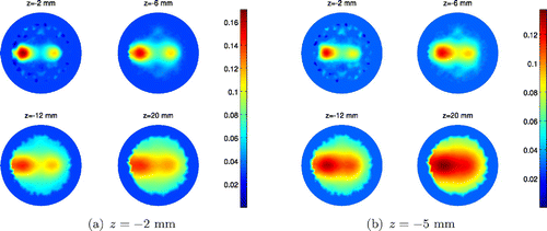
Fig. 6 Cross-sections of conductivity reconstruction for M15 at position 1 and M20 at position 3. The inclusion is (a) 2mm and (b) 5 mm below the sensing head.
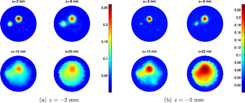
Fig. 6 Cross-sections of conductivity reconstruction for M15 at position 1 and M20 at position 3. The inclusion is (a) 2mm and (b) 5 mm below the sensing head.

Reprints and Corporate Permissions

Please note: Selecting permissions does not provide access to the full text of the article, please see our help page How do I view content?

To request a reprint or corporate permissions for this article, please click on the relevant link below:

Academic Permissions

Please note: Selecting permissions does not provide access to the full text of the article, please see our help page How do I view content?

Obtain permissions instantly via Rightslink by clicking on the button below:

If you are unable to obtain permissions via Rightslink, please complete and submit this Permissions form. For more information, please visit our Permissions help page.