Figures & data
Figure 1. Three-dimensional geometry.
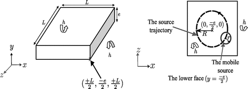
Figure 2. Heating flux .
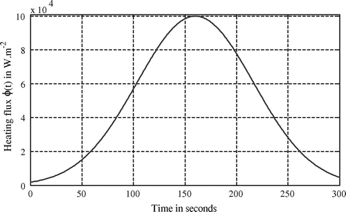
Table 1. Parameters for direct problem resolution.
Table 2. Cost function values for several iterations (fixed source).
Figure 3. Temperature evolution for the fixed heating source (direct problem).
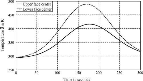
Figure 4. Sensors’ locations (upper face) and source trajectory (lower face).
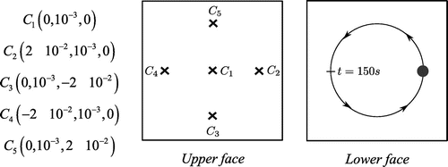
Figure 5. Temperature evolution on the upper face (mobile source – direct problem).
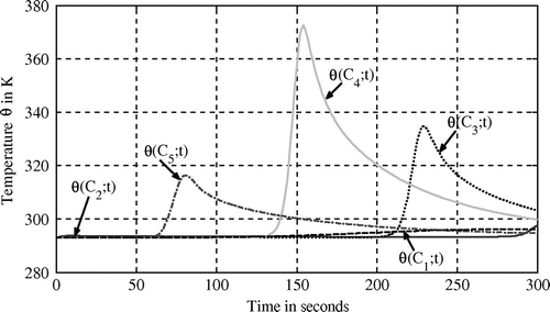
Figure 6. Basis functions .
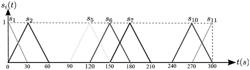
Figure 7. Tracking error evolution (Case 1).
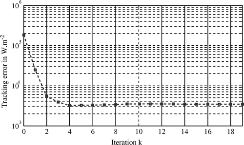
Figure 8. Identified heating flux (Case 1).
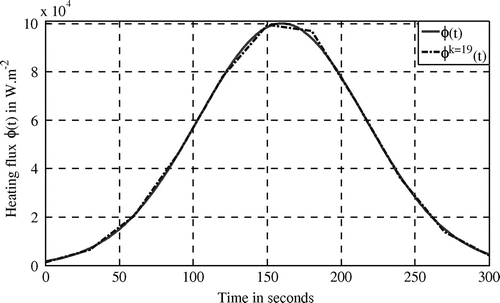
Figure 9. Identified heating flux (Case 2).
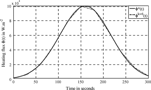
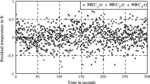
Figure 10. Residual temperature error (Case 2).
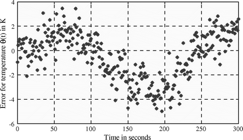
Figure 11. Tracking error evolution (Case 3).
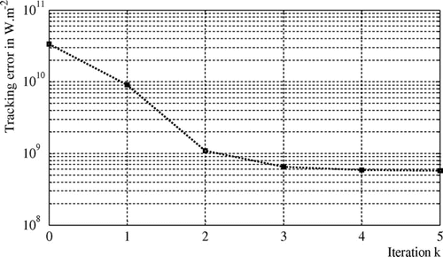
Figure 12. Identified heating flux (Case 3).
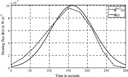
Figure 13. Disturbed measurements at (Case 4).
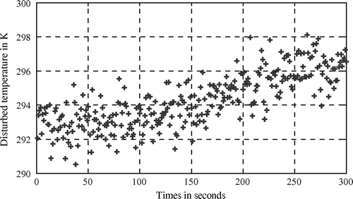
Table 3. Cost function values at each iteration (Case 4).
Figure 14. Heating flux identification (Case 4).
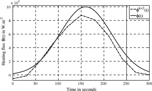
Figure 15. Residual temperature error (Case 4).
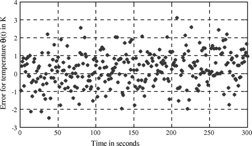
Table 4. Mobile source trajectory.
Table 5. Cost function values for several iterations (experimentation).
Figure 16. Sensors positions (upper face) and heating source trajectory (lower face).
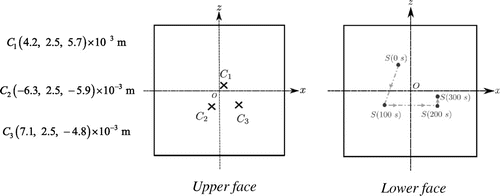
Figure 17. Measured (square) and calculated temperature.
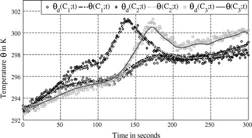
Figure 18. Identified experimental heating flux.
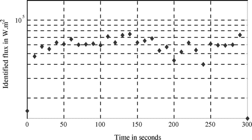
Figure 19. Residual temperature (experimentation).