450
Views
11
CrossRef citations to date
0
Altmetric
Articles

Seismic data reconstruction via weighted nuclear-norm minimization

, , &
Pages 277-291 | Received 17 Oct 2013, Accepted 29 Jan 2014, Published online: 14 Mar 2014

Figures & data

Figure 1. (a) Original seismic data X1. (b) Corrupted data with 50% missing traces.

Figure 1. (a) Original seismic data X1. (b) Corrupted data with 50% missing traces.

Figure 2. Reconstructions for X1 under δ=0. (a)–(d): Reconstructed 100th single traces via IST, LMaFit, WSST and WISD, respectively. Left-half part is the 100th trace comparison, while the right-half part is the corresponding reconstruction error comparison.
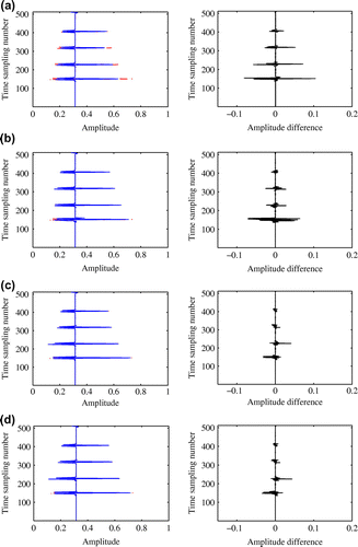
Figure 2. Reconstructions for X1 under δ=0. (a)–(d): Reconstructed 100th single traces via IST, LMaFit, WSST and WISD, respectively. Left-half part is the 100th trace comparison, while the right-half part is the corresponding reconstruction error comparison.

Table 1. The SNR and CPU times of reconstructions for X1 by four different algorithms with three different noise levels.

Table 2. The SNR and CPU times of reconstructions for X2 by four different algorithms with three different sampling ratios.

Table 3. The SNR and CPU times of reconstructions for X3 by four different algorithms with three different sampling ratios.

Figure 3. The SNR change of reconstructions by four different algorithms for X1 as the sampling ratio increases from 20 to 90%.
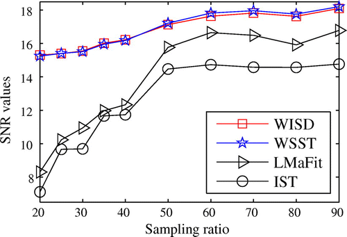
Figure 3. The SNR change of reconstructions by four different algorithms for X1 as the sampling ratio increases from 20 to 90%.

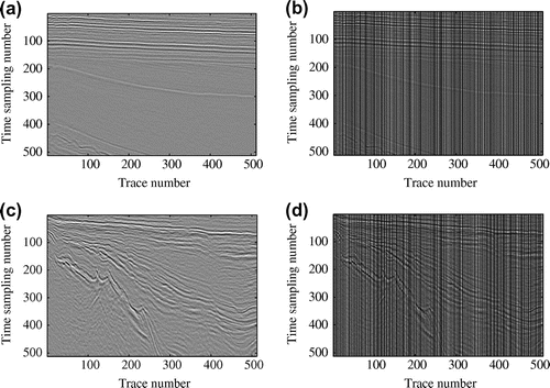
Figure 4. Left column: original data X2 (a) and X3 (c). Right column: (b) and (d) are the corresponding corrupted data with 50% traces missing for X2 and X3, respectively.

Figure 4. Left column: original data X2 (a) and X3 (c). Right column: (b) and (d) are the corresponding corrupted data with 50% traces missing for X2 and X3, respectively.

Figure 5. Reconstructions for X2. (a)–(d): Reconstructed eighth single traces via IST, LMaFit, WSST and WISD, respectively. Left-half part is the eighth trace comparison, while the right-half part is the corresponding reconstruction error comparison.
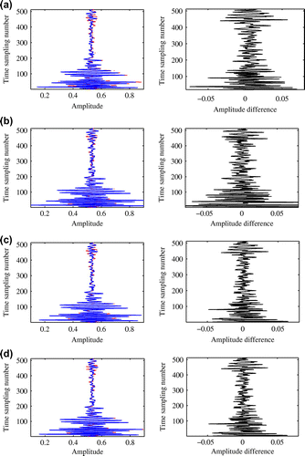
Figure 5. Reconstructions for X2. (a)–(d): Reconstructed eighth single traces via IST, LMaFit, WSST and WISD, respectively. Left-half part is the eighth trace comparison, while the right-half part is the corresponding reconstruction error comparison.
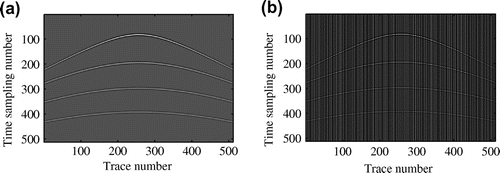
Figure 6. Reconstructions for X3. (a)–(d): Reconstructed central single traces via IST, LMaFit, WSST and WISD, respectively. Left-half part is the central trace comparison, while the right-half part is the corresponding reconstruction error comparison.
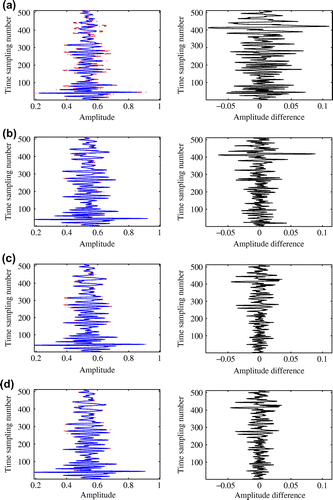
Figure 6. Reconstructions for X3. (a)–(d): Reconstructed central single traces via IST, LMaFit, WSST and WISD, respectively. Left-half part is the central trace comparison, while the right-half part is the corresponding reconstruction error comparison.

Figure 7. The SNR change of reconstructions by four different algorithms ((a) for X2 and (b) for X3) as the sampling ratio increases from 20 to 90%.

Figure 7. The SNR change of reconstructions by four different algorithms ((a) for X2 and (b) for X3) as the sampling ratio increases from 20 to 90%.

Reprints and Corporate Permissions

Please note: Selecting permissions does not provide access to the full text of the article, please see our help page How do I view content?

To request a reprint or corporate permissions for this article, please click on the relevant link below:

Academic Permissions

Please note: Selecting permissions does not provide access to the full text of the article, please see our help page How do I view content?

Obtain permissions instantly via Rightslink by clicking on the button below:

If you are unable to obtain permissions via Rightslink, please complete and submit this Permissions form. For more information, please visit our Permissions help page.