332
Views
3
CrossRef citations to date
0
Altmetric
Articles

Characterization of stress–strain behaviour of red blood cells (RBCs), part I: methodology development and application to healthy RBCs

&
Pages 913-931 | Received 25 Oct 2012, Accepted 22 Jul 2014, Published online: 04 Sep 2014

Figures & data

Figure 1. Force and diameter relationship from optical tweezers after Dao et al. [Citation1]: (a) Notation of axial and transverse directions, and (b) Continuum (FE) analyses use a hyperelastic material constitutive model with an initial shear modulus μ0.

Figure 1. Force and diameter relationship from optical tweezers after Dao et al. [Citation1]: (a) Notation of axial and transverse directions, and (b) Continuum (FE) analyses use a hyperelastic material constitutive model with an initial shear modulus μ0.

Figure 2. Transverse vs. axial diameter relationship from optical tweezers measurements of Dao et al. [Citation1] reinterpreted by the authors. See Figure for plot legend.

Figure 2. Transverse vs. axial diameter relationship from optical tweezers measurements of Dao et al. [Citation1] reinterpreted by the authors. See Figure 1 for plot legend.

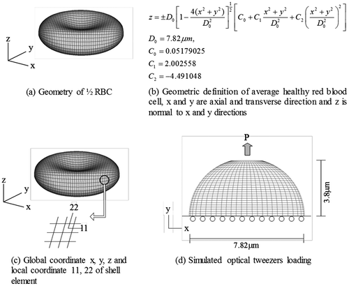
Figure 3. Schematic of simulated experiment.

Figure 3. Schematic of simulated experiment.

Figure 4. Force and diameter relationship from experiment and FE analyses with hyperelastic material (a) Initial shear modulus μ0 = 6.2, and (b) Initial shear modulus μ0 = 3.2.
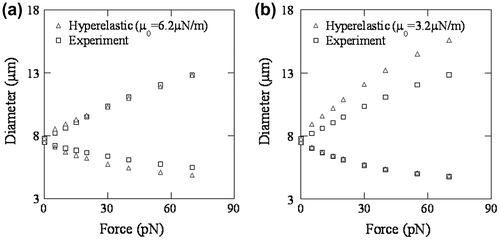
Figure 4. Force and diameter relationship from experiment and FE analyses with hyperelastic material (a) Initial shear modulus μ0 = 6.2, and (b) Initial shear modulus μ0 = 3.2.

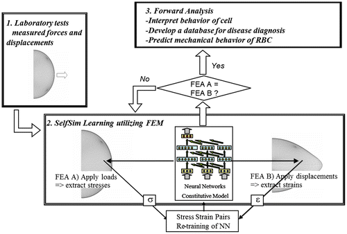
Figure 5. SelfSim analysis framework.

Figure 5. SelfSim analysis framework.

Figure 6. Global responses with extracted material model before and after SelfSim using synthetic target measurement generated from a hyperelastic material model representation of RBC: (a) Force-displacement, and (b) Transverse-axial displacement.
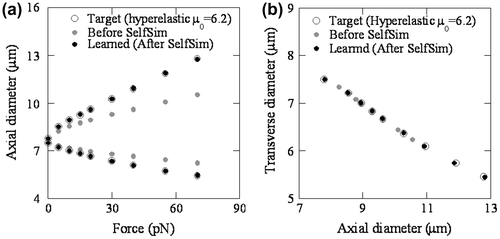
Figure 6. Global responses with extracted material model before and after SelfSim using synthetic target measurement generated from a hyperelastic material model representation of RBC: (a) Force-displacement, and (b) Transverse-axial displacement.

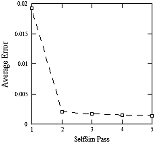
Figure 7. Average error of SelfSim passes.

Figure 7. Average error of SelfSim passes.

Figure 8. Comparison of target and extracted response after SelfSim using synthetic target measurement.
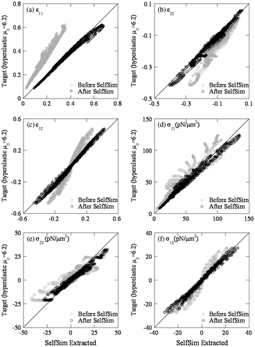
Figure 8. Comparison of target and extracted response after SelfSim using synthetic target measurement.

Figure 9. Comparison of extracted stress–strain response after SelfSim learning using synthetic target measurement and the target stress–strain response.
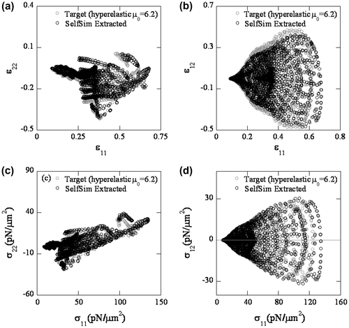
Figure 9. Comparison of extracted stress–strain response after SelfSim learning using synthetic target measurement and the target stress–strain response.

Figure 10. Maximum shear stress and shear strain from target and extracted response after SelfSim using synthetic target measurement.
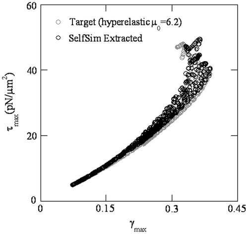
Figure 10. Maximum shear stress and shear strain from target and extracted response after SelfSim using synthetic target measurement.

Figure 11. In-plane shear modulus from the synthetic target and extracted response after SelfSim: (a) with maximum shear strain, and (b) with maximum shear stress.
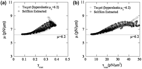
Figure 11. In-plane shear modulus from the synthetic target and extracted response after SelfSim: (a) with maximum shear strain, and (b) with maximum shear stress.
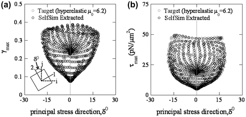
Figure 12. Principal stress direction of the synthetic target from hyperelastic material model and extracted response after SelfSim: (a) with maximum shear strain, and (b) with maximum shear stress.

Figure 12. Principal stress direction of the synthetic target from hyperelastic material model and extracted response after SelfSim: (a) with maximum shear strain, and (b) with maximum shear stress.

Figure 13. In-plane shear modulus with principal stress direction of the synthetic target from hyperelastic material model and extracted response after SelfSim.
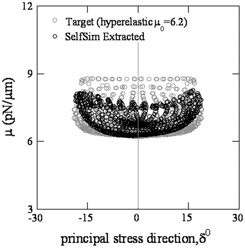
Figure 13. In-plane shear modulus with principal stress direction of the synthetic target from hyperelastic material model and extracted response after SelfSim.

Figure 14. Global responses with extracted material model before and after SelfSim using experimental measurements of healthy RBC: (a) force–displacement, and (b) transverse-axial displacement.
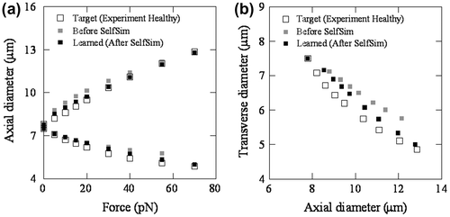
Figure 14. Global responses with extracted material model before and after SelfSim using experimental measurements of healthy RBC: (a) force–displacement, and (b) transverse-axial displacement.

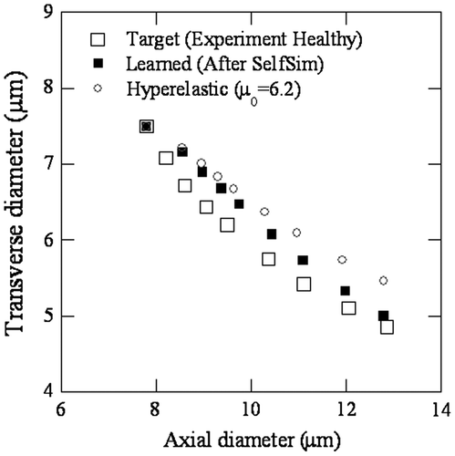
Figure 15. Transverse–axial relationship of extracted material model with experimental data.

Figure 15. Transverse–axial relationship of extracted material model with experimental data.

Figure 16. Comparison of hyperelastic and extracted response after SelfSim using experiment data on healthy RBC.
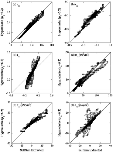
Figure 16. Comparison of hyperelastic and extracted response after SelfSim using experiment data on healthy RBC.

Figure 17. Comparison of extracted stress–strain response after SelfSim using experiment data of healthy RBCs and the synthetic stress–strain response generated from a hyperelastic material model.
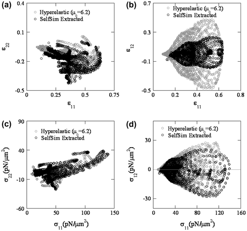
Figure 17. Comparison of extracted stress–strain response after SelfSim using experiment data of healthy RBCs and the synthetic stress–strain response generated from a hyperelastic material model.

Figure 18. Maximum shear stress and shear strain from hyperelastic and extracted response after SelfSim using experiment data on healthy RBCs.
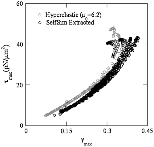
Figure 18. Maximum shear stress and shear strain from hyperelastic and extracted response after SelfSim using experiment data on healthy RBCs.

Figure 19. In-plane shear modulus from hyperelastic and extracted response after SelfSim using experiment data on healthy RBCs: (a) with maximum shear strain, and (b) with maximum shear stress.
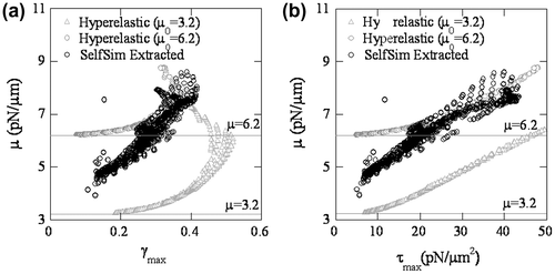
Figure 19. In-plane shear modulus from hyperelastic and extracted response after SelfSim using experiment data on healthy RBCs: (a) with maximum shear strain, and (b) with maximum shear stress.
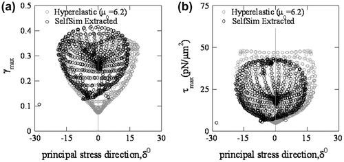
Figure 20. Principal stress direction from hyperelastic and extracted response after SelfSim using experiment data on healthy RBCs: (a) with maximum shear strain, and (b) with maximum shear stress.

Figure 20. Principal stress direction from hyperelastic and extracted response after SelfSim using experiment data on healthy RBCs: (a) with maximum shear strain, and (b) with maximum shear stress.

Figure 21. In-plane shear modulus with principal stress direction from hyperelastic and extracted response after SelfSim using experiment data on healthy RBCs.
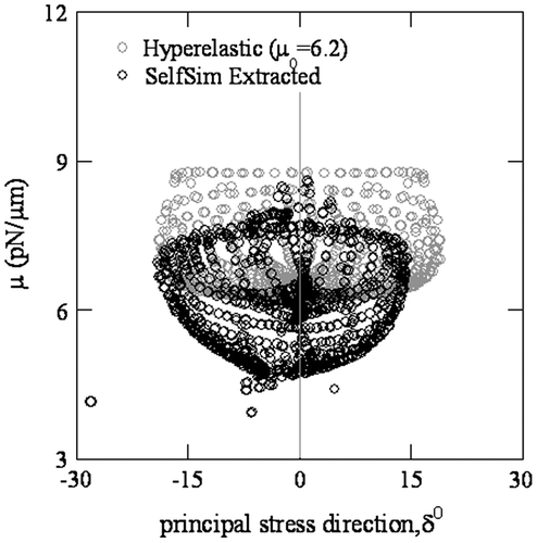
Figure 21. In-plane shear modulus with principal stress direction from hyperelastic and extracted response after SelfSim using experiment data on healthy RBCs.
Reprints and Corporate Permissions

Please note: Selecting permissions does not provide access to the full text of the article, please see our help page How do I view content?

To request a reprint or corporate permissions for this article, please click on the relevant link below:

Academic Permissions

Please note: Selecting permissions does not provide access to the full text of the article, please see our help page How do I view content?

Obtain permissions instantly via Rightslink by clicking on the button below:

If you are unable to obtain permissions via Rightslink, please complete and submit this Permissions form. For more information, please visit our Permissions help page.