267
Views
0
CrossRef citations to date
0
Altmetric
Articles

Riemannian methods for optimization in a shape space of triangular meshes

&
Pages 1011-1039 | Received 08 Apr 2013, Accepted 20 Oct 2014, Published online: 17 Nov 2014

Figures & data

Table 1. Definitions of some frequently used notations.

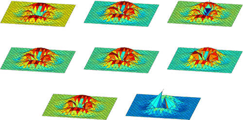
Figure 1. A free geodetic propagation with different Riemannian metrics. From top to bottom and left to right: Initial shape, Euclidiean, H0-, H1-, H2-, H3-, H5- and H8-metric.

Figure 1. A free geodetic propagation with different Riemannian metrics. From top to bottom and left to right: Initial shape, Euclidiean, H0-, H1-, H2-, H3-, H5- and H8-metric.

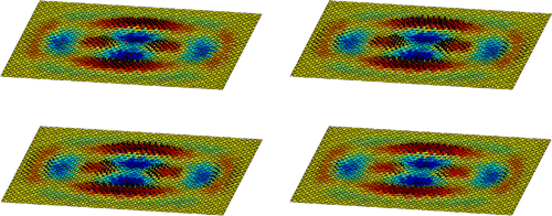
Figure 2. A shape together with the descent direction for different Riemannian metrics. From top to bottom and left to right: Euclidiean, H0-, H1- and H2-metric.

Figure 2. A shape together with the descent direction for different Riemannian metrics. From top to bottom and left to right: Euclidiean, H0-, H1- and H2-metric.

Figure 3. The synthetic shape, its shading image, the initial shape and its reconstruction using the SSD-method.
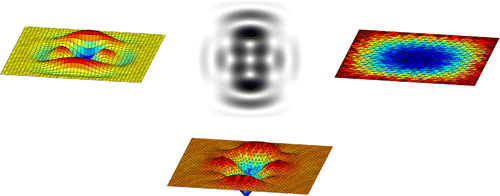
Figure 3. The synthetic shape, its shading image, the initial shape and its reconstruction using the SSD-method.

Figure 4. Reconstruction of the synthetic shape with the GSD-method using different Riemannian metrics. From left to right: Euclidean, H0- and H2-metric.

Figure 4. Reconstruction of the synthetic shape with the GSD-method using different Riemannian metrics. From left to right: Euclidean, H0- and H2-metric.

Figure 5. Reconstruction of the synthetic shape with the GNCG-method using different Riemannian metrics. From left to right: Euclidean, H0- and H2-metric.

Figure 5. Reconstruction of the synthetic shape with the GNCG-method using different Riemannian metrics. From left to right: Euclidean, H0- and H2-metric.

Figure 6. Reconstruction of the synthetic shape using the GSD-method, the Euclidean metric and an oblique light source l/l. From left to right: l=(0.1,0,1), l=(0,0.1,1).

Figure 6. Reconstruction of the synthetic shape using the GSD-method, the Euclidean metric and an oblique light source l/‖l‖. From left to right: l=(0.1,0,1), l=(0,0.1,1).

Figure 7. The bottom of the ceramic cup, its shading image, the initial shape and its reconstruction using the SSD-method.
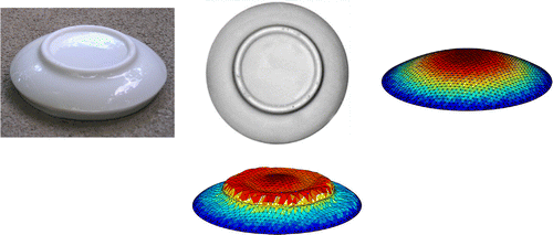
Figure 7. The bottom of the ceramic cup, its shading image, the initial shape and its reconstruction using the SSD-method.

Figure 8. Reconstruction of the bottom of the ceramic cup with the GSD-method using different Riemannian metrics. From left to right: Euclidean, H0- and H2-metric.

Figure 8. Reconstruction of the bottom of the ceramic cup with the GSD-method using different Riemannian metrics. From left to right: Euclidean, H0- and H2-metric.

Figure 9. Reconstruction of the bottom of the ceramic cup with the GNCG-method using different Riemannian metrics. From left to right: Euclidean, H0- and H2-metric.

Figure 9. Reconstruction of the bottom of the ceramic cup with the GNCG-method using different Riemannian metrics. From left to right: Euclidean, H0- and H2-metric.

Figure 10. The shading image of the face, the initial shape and its reconstruction using the SSD-method.

Figure 10. The shading image of the face, the initial shape and its reconstruction using the SSD-method.

Figure 11. Reconstruction of the face with the GSD-method using different Riemannian metrics. From left to right: Euclidean, H0- and H2-metric.

Figure 11. Reconstruction of the face with the GSD-method using different Riemannian metrics. From left to right: Euclidean, H0- and H2-metric.

Figure 12. Reconstruction of the face with the GNCG-method using different Riemannian metrics. From left to right: Euclidean, H0- and H2-metric.

Figure 12. Reconstruction of the face with the GNCG-method using different Riemannian metrics. From left to right: Euclidean, H0- and H2-metric.

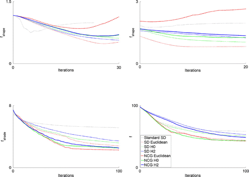
Figure 13. Convergence of several optimization techniques in different situations. Top left: Synthetic shape (coarse-grid optimization). Top right: Synthetic shape (fine-grid optimization). Bottom left: Ceramic cup. Bottom right: Face. The legend applies to all four plots.

Figure 13. Convergence of several optimization techniques in different situations. Top left: Synthetic shape (coarse-grid optimization). Top right: Synthetic shape (fine-grid optimization). Bottom left: Ceramic cup. Bottom right: Face. The legend applies to all four plots.

Reprints and Corporate Permissions

Please note: Selecting permissions does not provide access to the full text of the article, please see our help page How do I view content?

To request a reprint or corporate permissions for this article, please click on the relevant link below:

Academic Permissions

Please note: Selecting permissions does not provide access to the full text of the article, please see our help page How do I view content?

Obtain permissions instantly via Rightslink by clicking on the button below:

If you are unable to obtain permissions via Rightslink, please complete and submit this Permissions form. For more information, please visit our Permissions help page.