630
Views
7
CrossRef citations to date
0
Altmetric
Articles

A three-dimensional image reconstruction algorithm for electrical impedance tomography using planar electrode arrays

, &
Pages 471-491 | Received 24 Sep 2015, Accepted 15 Mar 2016, Published online: 06 Apr 2016

Figures & data

Figure 1. Layout of the rectangular electrode array of the latest prototype developed at the University of Mainz in collaboration with Oxford Brookes University:
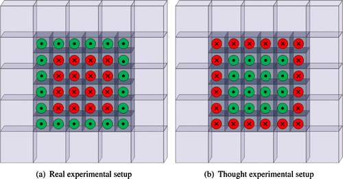
are the active electrodes used for current injection, and
are the passive electrodes used for potential measurements.

Figure 1. Layout of the rectangular electrode array of the latest prototype developed at the University of Mainz in collaboration with Oxford Brookes University: Display full size are the active electrodes used for current injection, and Display full size are the passive electrodes used for potential measurements.

Figure 2. Voxel configuration: are the active electrodes, are the passive electrodes, and P1-P5 denote the positions in the xy-plane where inclusions were placed in our numerical simulations.
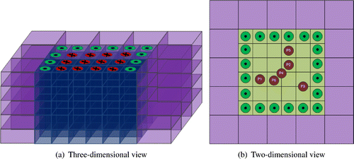
Figure 2. Voxel configuration: are the active electrodes, are the passive electrodes, and P1-P5 denote the positions in the xy-plane where inclusions were placed in our numerical simulations.

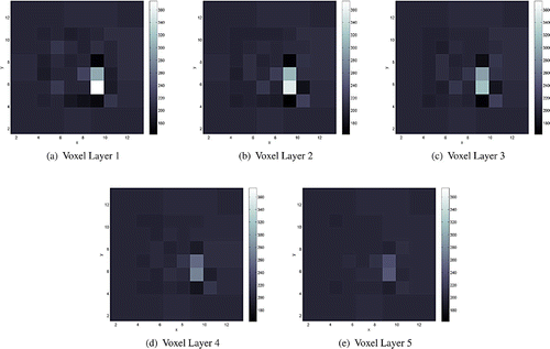
Figure 3. Conductivity reconstructions for a cylindrical object of radius R25 of conductivity 800 mS/m placed at position P1 and z=-2 mm. The thick continuous line in (e) marks the position and the height of the inclusion along the z-axis.
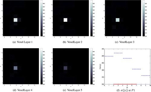
Figure 3. Conductivity reconstructions for a cylindrical object of radius R25 of conductivity 800 mS/m placed at position P1 and z=-2 mm. The thick continuous line in (e) marks the position and the height of the inclusion along the z-axis.
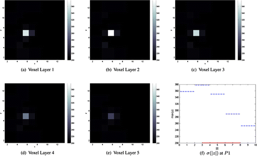
Figure 4. Conductivity reconstructions for a cylindrical object of radius R25 of conductivity 800 mS/m placed at position P1 and z=-3 mm. The thick continuous line in (e) marks the position and the height of the inclusion along the z-axis.
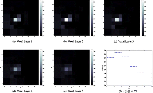
Figure 4. Conductivity reconstructions for a cylindrical object of radius R25 of conductivity 800 mS/m placed at position P1 and z=-3 mm. The thick continuous line in (e) marks the position and the height of the inclusion along the z-axis.
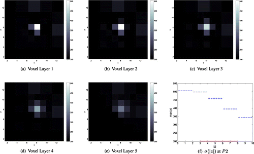
Figure 5. Conductivity reconstructions for a cylindrical object of radius R25 of conductivity 800 mS/m placed at position P1 and z=-6 mm. The thick continuous line in (e) marks the position and the height of the inclusion along the z-axis.
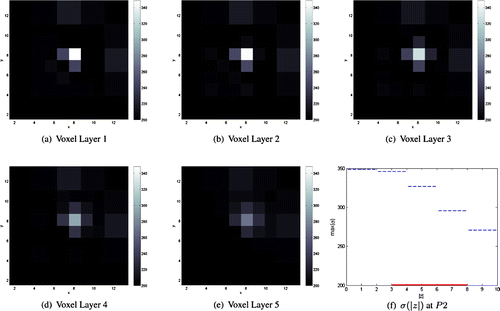
Figure 5. Conductivity reconstructions for a cylindrical object of radius R25 of conductivity 800 mS/m placed at position P1 and z=-6 mm. The thick continuous line in (e) marks the position and the height of the inclusion along the z-axis.
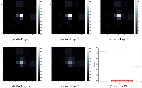
Figure 6. Conductivity reconstructions for a cylindrical object of radius R35 of conductivity 800 mS/m placed at position P2 and z=-3 mm. The thick continuous line in (e) marks the position and the height of the inclusion along the z-axis.
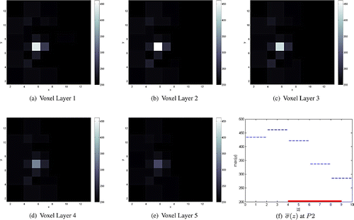
Figure 6. Conductivity reconstructions for a cylindrical object of radius R35 of conductivity 800 mS/m placed at position P2 and z=-3 mm. The thick continuous line in (e) marks the position and the height of the inclusion along the z-axis.
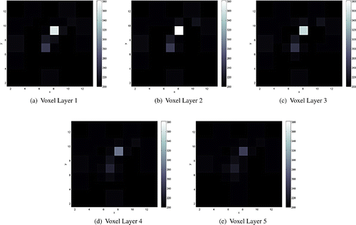
Figure 7. Conductivity reconstructions for a cylindrical object of radius R25 of conductivity 800 mS/m placed at position P2 and z=-3 mm. The thick continuous line in (e) marks the position and the height of the inclusion along the z-axis.
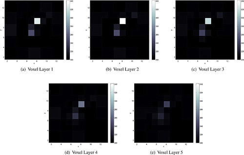
Figure 7. Conductivity reconstructions for a cylindrical object of radius R25 of conductivity 800 mS/m placed at position P2 and z=-3 mm. The thick continuous line in (e) marks the position and the height of the inclusion along the z-axis.

Figure 8. Conductivity reconstructions for a cylindrical object of radius R15 of conductivity 800mS/m placed at position P2 and z=-3 mm. The thick continuous line in (e) marks the position and the height of the inclusion along the z-axis.

Figure 8. Conductivity reconstructions for a cylindrical object of radius R15 of conductivity 800mS/m placed at position P2 and z=-3 mm. The thick continuous line in (e) marks the position and the height of the inclusion along the z-axis.

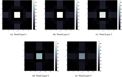
Figure 9. Conductivity reconstructions for a cylindrical object of radius R25 of conductivity 800 mS/m placed at position P3 and z=-3 mm.

Figure 9. Conductivity reconstructions for a cylindrical object of radius R25 of conductivity 800 mS/m placed at position P3 and z=-3 mm.

Figure 10. Conductivity reconstructions for a cylindrical object of radius R25 of conductivity 800 mS/m placed at position P4 and z=-3 mm.

Figure 10. Conductivity reconstructions for a cylindrical object of radius R25 of conductivity 800 mS/m placed at position P4 and z=-3 mm.

Figure 11. Conductivity reconstructions for a cylindrical object of radius R35 of conductivity 800 mS/m placed at position P1 and z=-4 mm in the presence of a resistive medium (50 mS/m) in Voxel Layer 1. The thick continuous line in (e) marks the position and the height of the inclusion along the z-axis.

Figure 11. Conductivity reconstructions for a cylindrical object of radius R35 of conductivity 800 mS/m placed at position P1 and z=-4 mm in the presence of a resistive medium (50 mS/m) in Voxel Layer 1. The thick continuous line in (e) marks the position and the height of the inclusion along the z-axis.

Figure 12. Conductivity reconstructions for two cylindrical objects of radii R25 and R15 of conductivities 800 mS/m placed at positions P5 and P6, respectively, and z=-3 mm.

Figure 12. Conductivity reconstructions for two cylindrical objects of radii R25 and R15 of conductivities 800 mS/m placed at positions P5 and P6, respectively, and z=-3 mm.

Figure 13. Conductivity reconstructions for two cylindrical objects, one of radius R25 and of conductivity 600 mS/m, and the other of radius R15 and of conductivity 800 mS/m, placed at positions P5 and P6, respectively, and z=-3 mm.

Figure 13. Conductivity reconstructions for two cylindrical objects, one of radius R25 and of conductivity 600 mS/m, and the other of radius R15 and of conductivity 800 mS/m, placed at positions P5 and P6, respectively, and z=-3 mm.

Reprints and Corporate Permissions

Please note: Selecting permissions does not provide access to the full text of the article, please see our help page How do I view content?

To request a reprint or corporate permissions for this article, please click on the relevant link below:

Academic Permissions

Please note: Selecting permissions does not provide access to the full text of the article, please see our help page How do I view content?

Obtain permissions instantly via Rightslink by clicking on the button below:

If you are unable to obtain permissions via Rightslink, please complete and submit this Permissions form. For more information, please visit our Permissions help page.