Figures & data
Figure 1. Discrepancy of PAT than MAT for two same-located impacts when (a) impact location 1 and sensor 4 (b) impact location 14 and sensor 5.
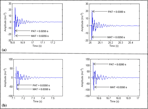
Figure 2. (a) Deviation of TC (at sensor 1) due to ambient noise for two separate impacts at location 3 (b) Non-variety of TC at sensors 10 and 12 for impact at location 3. (sensor’s radial distance difference from impact source = 4.5 cm)
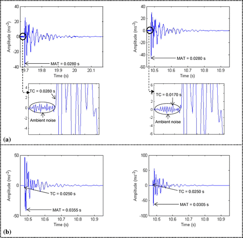
Figure 3. General topology of MLP.
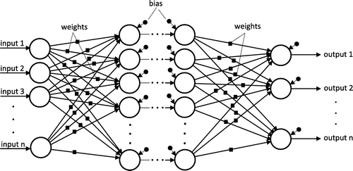
Figure 4. Experimental set-up for impact identification study.
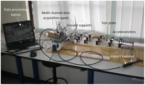
Figure 5. Arrangement of the sensors and impact locations.
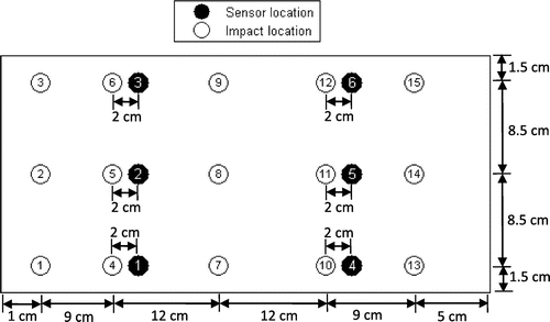
Figure 6. Impact localization and impact quantification scheme.
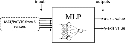
Figure 7. Structure and distribution of data in different stages.
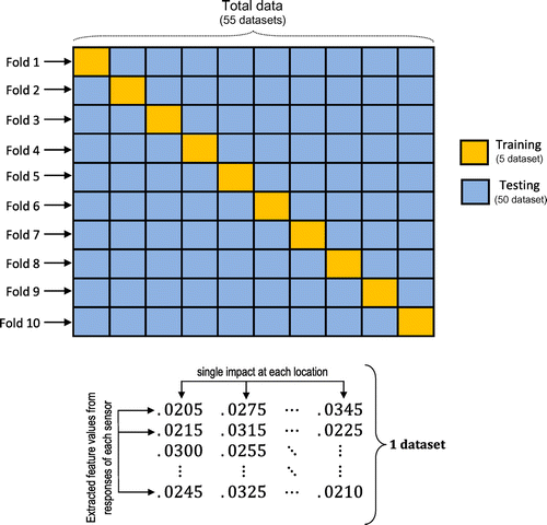
Figure 8. Schematic diagram of the experimental procedure.
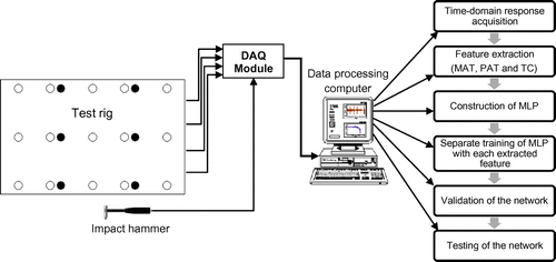
Table 1. The effect of hidden neurons with different features and subsamples.
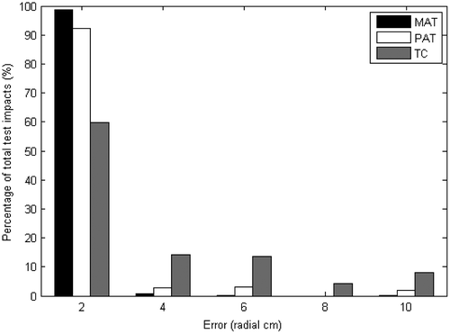
Figure 9. Impact localization error (radial cm) vs. no. of test impacts using MAT.
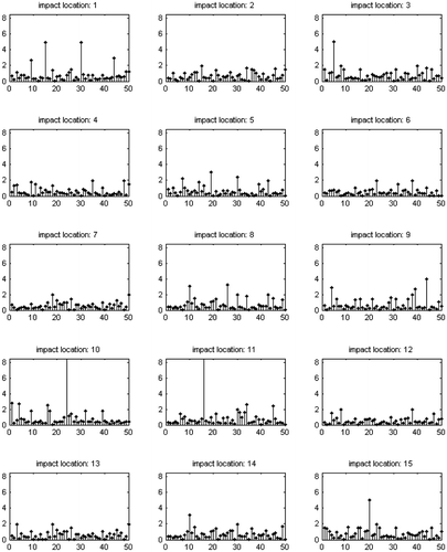
Figure 10. Impact localization error (radial cm) vs. no. of test impacts using PAT.
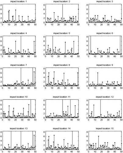
Figure 11. Impact localization error (radial cm) vs. no. of test impacts using TC.
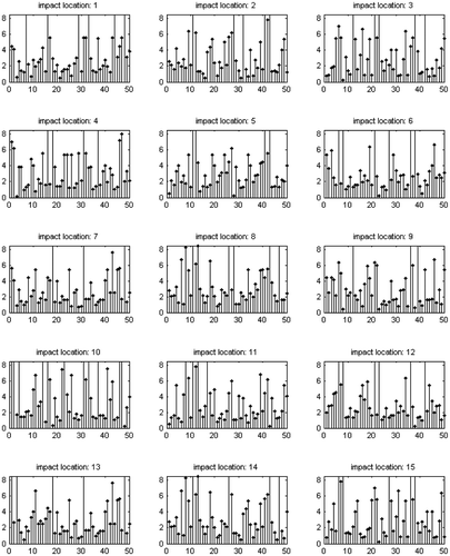
Table 2. Mean approximation error at individual locations.
Figure 12. Performance histogram of the selected features for impact localization (subsample 4).