389
Views
2
CrossRef citations to date
0
Altmetric
Original Articles

Optical property inversion of biological materials using Fourier series expansion and LS-SVM for hyperspectral imaging

, , &
Pages 1019-1036 | Received 14 Dec 2016, Accepted 04 Sep 2017, Published online: 21 Sep 2017

Figures & data

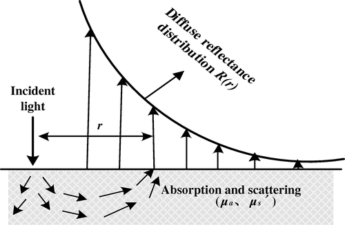
Figure 1. Schematic of the steady-state spatially resolved measurement technique.

Figure 1. Schematic of the steady-state spatially resolved measurement technique.

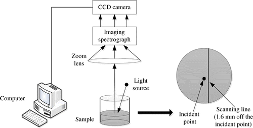
Figure 2. Acquisition of hyperspectral images for liquid phantoms.

Figure 2. Acquisition of hyperspectral images for liquid phantoms.

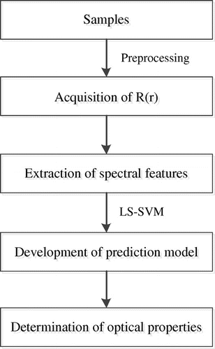
Figure 3. Flowchart of the model development for predicting optical properties.

Figure 3. Flowchart of the model development for predicting optical properties.

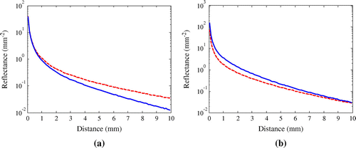
Figure 4. Comparison of the spatially resolved diffuse reflectance profiles obtained from MC simulation: (a) μa=0.04cm-1, μs=4cm-1 (dotted line) and μa=0.29cm-1, μs=4cm-1 (solid line) (b) μa=0.04cm-1, μs=8cm-1 (dotted line) and μa=0.04cm-1 μs=12cm-1 (solid line).

Figure 4. Comparison of the spatially resolved diffuse reflectance profiles obtained from MC simulation: (a) μa=0.04cm-1, μs′=4cm-1 (dotted line) and μa=0.29cm-1, μs′=4cm-1 (solid line) (b) μa=0.04cm-1, μs′=8cm-1 (dotted line) and μa=0.04cm-1 μs′=12cm-1 (solid line).

Figure 5. Relative errors of (a) μa and (b) μs with different combinations of the Fourier coefficients.
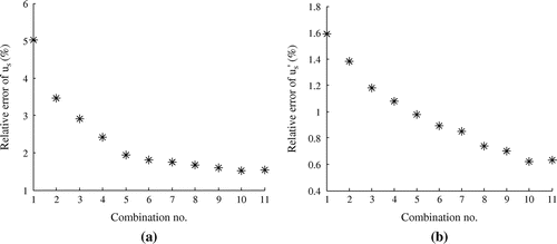
Figure 5. Relative errors of (a) μa and (b) μs′ with different combinations of the Fourier coefficients.

Table 1. Calibration and prediction results (in percent) for MC simulation.Table Footnotea

Table 2. Calibration and prediction results (in percent) for MC simulation with different noise levels.Table Footnotea

Figure 6. (a) Hyperspectral image of a blue dye liquid phantom and (b) diffuse reflectance profiles for the three selected wavelengths.
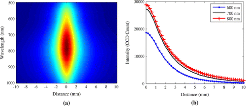
Figure 6. (a) Hyperspectral image of a blue dye liquid phantom and (b) diffuse reflectance profiles for the three selected wavelengths.

Table 3. Calibration and prediction results (in percent) for liquid phantoms using experimental data.Table Footnotea

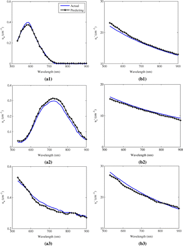
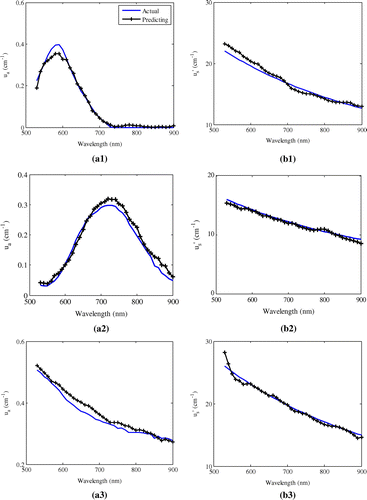
Figure 7. The prediction results of μa and μs for three liquid phantoms using experimental data: (a1) μa of blue dye, (b1) μs of blue dye, (a2) μa of green dye, (b2) μs of green dye, (a3) μa of black ink and (b3) μs of black ink.

Figure 7. The prediction results of μa and μs′ for three liquid phantoms using experimental data: (a1) μa of blue dye, (b1) μs′ of blue dye, (a2) μa of green dye, (b2) μs′ of green dye, (a3) μa of black ink and (b3) μs′ of black ink.

Table 4. Calibration and prediction results (in percent) for liquid phantoms using MC simulation data.Table Footnotea

Figure 8. The prediction results of μa and μs for three simulation phantoms using MC simulation data: (a1) μa of blue dye, (b1) μs of blue dye, (a2) μa of green dye, (b2) μs of green dye, (a3) μa of black ink and (b3) μs of black ink.

Figure 8. The prediction results of μa and μs′ for three simulation phantoms using MC simulation data: (a1) μa of blue dye, (b1) μs′ of blue dye, (a2) μa of green dye, (b2) μs′ of green dye, (a3) μa of black ink and (b3) μs′ of black ink.

Reprints and Corporate Permissions

Please note: Selecting permissions does not provide access to the full text of the article, please see our help page How do I view content?

To request a reprint or corporate permissions for this article, please click on the relevant link below:

Academic Permissions

Please note: Selecting permissions does not provide access to the full text of the article, please see our help page How do I view content?

Obtain permissions instantly via Rightslink by clicking on the button below:

If you are unable to obtain permissions via Rightslink, please complete and submit this Permissions form. For more information, please visit our Permissions help page.