398
Views
2
CrossRef citations to date
0
Altmetric
Articles

Structural performance evaluation of an aged structure using a modified plasticity model in inverse solution method

, &
Pages 1326-1355 | Received 09 Apr 2017, Accepted 10 Oct 2017, Published online: 22 Nov 2017

Figures & data

Figure 1. Uniaxial compressive stress–strain model presented by Hsu and Hsu [Citation23].

Figure 1. Uniaxial compressive stress–strain model presented by Hsu and Hsu [Citation23].

Figure 2. Biaxial strength of concrete – Kupfer and Hilsdorf [Citation25].

Figure 2. Biaxial strength of concrete – Kupfer and Hilsdorf [Citation25].

Figure 3. ‘Tensile behaviour’ for CDP model – Enochsson et al. [Citation27].

Figure 3. ‘Tensile behaviour’ for CDP model – Enochsson et al. [Citation27].

Figure 4. Hyperbolic Drucker–Prager flow potential function-Abaqus theory manual, 6.11 [Citation28].

Figure 4. Hyperbolic Drucker–Prager flow potential function-Abaqus theory manual, 6.11 [Citation28].

Figure 5. ‘Tensile behaviour’ for CDP model – Wahalathantri et al. [Citation24].

Figure 5. ‘Tensile behaviour’ for CDP model – Wahalathantri et al. [Citation24].

Figure 6. Flowchart of performance of CDP model.

Figure 6. Flowchart of performance of CDP model.

Table 1. Variables used in inverse analyses.

Figure 7. Solution procedure.

Figure 7. Solution procedure.

Figure 8. Dez Dam subdivisions separated by contraction joints.

Figure 8. Dez Dam subdivisions separated by contraction joints.

Figure 9. Dez Dam section.

Figure 9. Dez Dam section.

Figure 10. FE Model of the Dez Dam and its support.

Figure 10. FE Model of the Dez Dam and its support.

Table 2. Element library of the dam–reservoir–foundation model.

Table 3. Long-term elastic stiffness components of the Dez Dam.

Figure 11. Long-term variations of the out-of-plane elastic modulus.

Figure 11. Long-term variations of the out-of-plane elastic modulus.

Figure 12. Long-term variations of the in-plane elastic modulus.

Figure 12. Long-term variations of the in-plane elastic modulus.

Figure 13. Long-term variations of the compressive strength of Dez Dam’s concrete.

Figure 13. Long-term variations of the compressive strength of Dez Dam’s concrete.

Figure 14. Change of Young’s moduli over time at top and bottom of the dam in zone 1.

Figure 14. Change of Young’s moduli over time at top and bottom of the dam in zone 1.

Figure 15. Change of Young’s moduli over time at top and bottom of the dam in zone 9.

Figure 15. Change of Young’s moduli over time at top and bottom of the dam in zone 9.

Figure A1. Variations of water level of reservoir and temperature throughout the Year 1965 – blue line denotes water levels of reservoir, red line indicates temperature values at downstream face, green line shows temperature values at upstream face of the Dez Dam and two dotted vertical lines present two days selected for performing thermal inverse analysis.
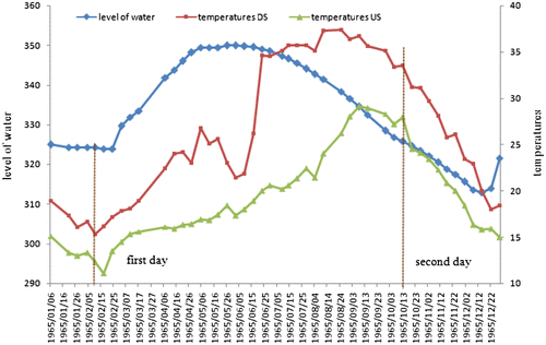
Figure A1. Variations of water level of reservoir and temperature throughout the Year 1965 – blue line denotes water levels of reservoir, red line indicates temperature values at downstream face, green line shows temperature values at upstream face of the Dez Dam and two dotted vertical lines present two days selected for performing thermal inverse analysis.
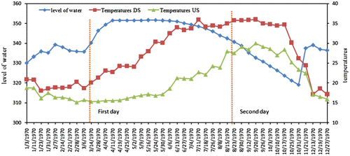
Figure A2. Variations of water level of reservoir and temperature throughout the Year 1970 – blue line denotes water levels of reservoir, red line indicates temperature values at downstream face and green line shows temperature values at upstream face of the Dez Dam and two dotted vertical lines present two days selected for performing thermal inverse analysis.
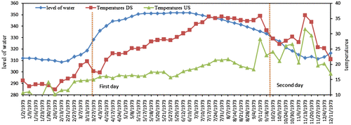
Figure A2. Variations of water level of reservoir and temperature throughout the Year 1970 – blue line denotes water levels of reservoir, red line indicates temperature values at downstream face and green line shows temperature values at upstream face of the Dez Dam and two dotted vertical lines present two days selected for performing thermal inverse analysis.
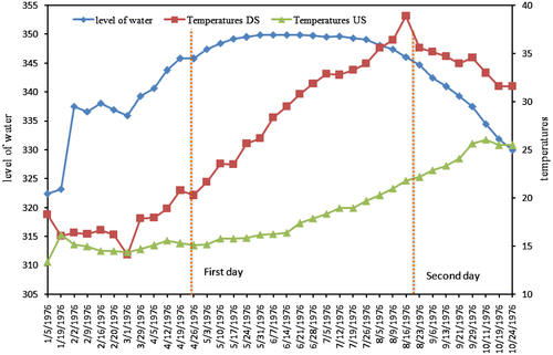
Figure A3. Variations of water level of reservoir and temperature throughout the Year 1973 – blue line denotes water levels of reservoir, red line indicates temperature values at downstream face and green line shows temperature values at upstream face of the Dez Dam and two dotted vertical lines present two days selected for performing thermal inverse analysis.
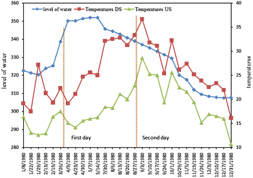
Figure A3. Variations of water level of reservoir and temperature throughout the Year 1973 – blue line denotes water levels of reservoir, red line indicates temperature values at downstream face and green line shows temperature values at upstream face of the Dez Dam and two dotted vertical lines present two days selected for performing thermal inverse analysis.
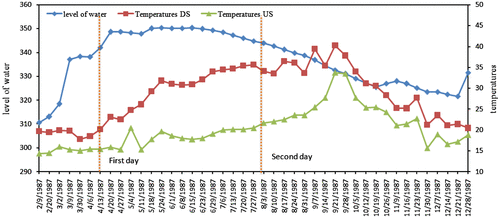
Figure A4. Variations of water level of reservoir and temperature throughout the Year 1976 – blue line denotes water levels of reservoir, red line indicates temperature values at downstream face and green line shows temperature values at upstream face of the Dez Dam and two dotted vertical lines present two days selected for performing thermal inverse analysis.
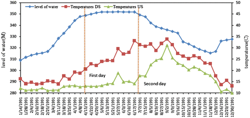
Figure A4. Variations of water level of reservoir and temperature throughout the Year 1976 – blue line denotes water levels of reservoir, red line indicates temperature values at downstream face and green line shows temperature values at upstream face of the Dez Dam and two dotted vertical lines present two days selected for performing thermal inverse analysis.

Figure A5. Variations of water level of reservoir and temperature throughout the Year 1980 – blue line denotes water levels of reservoir, red line indicates temperature values at downstream face and green line shows temperature values at upstream face of the Dez Dam and two dotted vertical lines present two days selected for performing thermal inverse analysis.
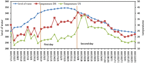
Figure A5. Variations of water level of reservoir and temperature throughout the Year 1980 – blue line denotes water levels of reservoir, red line indicates temperature values at downstream face and green line shows temperature values at upstream face of the Dez Dam and two dotted vertical lines present two days selected for performing thermal inverse analysis.
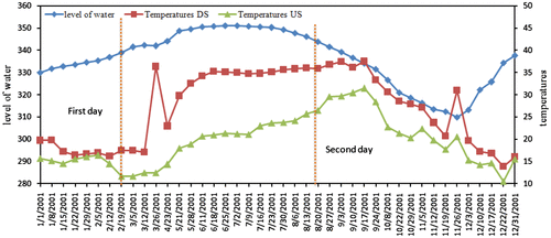
Figure A6. Variations of water level of reservoir and temperature throughout the Year 1987 – blue line denotes water levels of reservoir, red line indicates temperature values at downstream face and green line shows temperature values at upstream face of the Dez Dam and two dotted vertical lines present two days selected for performing thermal inverse analysis.
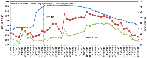
Figure A6. Variations of water level of reservoir and temperature throughout the Year 1987 – blue line denotes water levels of reservoir, red line indicates temperature values at downstream face and green line shows temperature values at upstream face of the Dez Dam and two dotted vertical lines present two days selected for performing thermal inverse analysis.
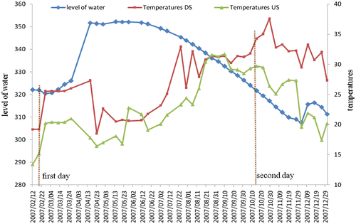
Figure A7. Variations of water level of reservoir and temperature throughout the Year 1991 – blue line denotes water levels of reservoir, red line indicates temperature values at downstream face and green line shows temperature values at upstream face of the Dez Dam and two dotted vertical lines present two days selected for performing thermal inverse analysis.
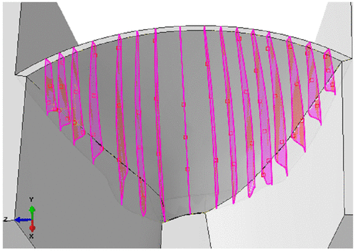
Figure A7. Variations of water level of reservoir and temperature throughout the Year 1991 – blue line denotes water levels of reservoir, red line indicates temperature values at downstream face and green line shows temperature values at upstream face of the Dez Dam and two dotted vertical lines present two days selected for performing thermal inverse analysis.
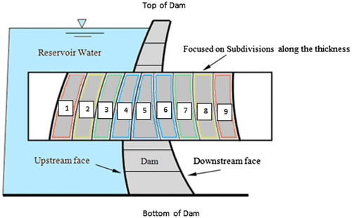
Figure A8. Variations of water level of reservoir and temperature throughout the Year 1995 – blue line denotes water levels of reservoir, red line indicates temperature values at downstream face and green line shows temperature values at upstream face of the Dez Dam and two dotted vertical lines present two days selected for performing thermal inverse analysis.
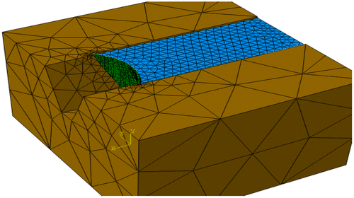
Figure A8. Variations of water level of reservoir and temperature throughout the Year 1995 – blue line denotes water levels of reservoir, red line indicates temperature values at downstream face and green line shows temperature values at upstream face of the Dez Dam and two dotted vertical lines present two days selected for performing thermal inverse analysis.

Figure A9. Variations of water level of reservoir and temperature throughout the Year 1999 – blue line denotes water levels of reservoir, red line indicates temperature values at downstream face and green line shows temperature values at upstream face of the Dez Dam and two dotted vertical lines present two days selected for performing thermal inverse analysis.

Figure A9. Variations of water level of reservoir and temperature throughout the Year 1999 – blue line denotes water levels of reservoir, red line indicates temperature values at downstream face and green line shows temperature values at upstream face of the Dez Dam and two dotted vertical lines present two days selected for performing thermal inverse analysis.

Figure A10. Variations of water level of reservoir and temperature throughout the Year 2001 – blue line denotes water levels of reservoir, red line indicates temperature values at downstream face and green line shows temperature values at upstream face of the Dez Dam and two dotted vertical lines present two days selected for performing thermal inverse analysis.

Figure A10. Variations of water level of reservoir and temperature throughout the Year 2001 – blue line denotes water levels of reservoir, red line indicates temperature values at downstream face and green line shows temperature values at upstream face of the Dez Dam and two dotted vertical lines present two days selected for performing thermal inverse analysis.

Figure A11. Variations of water level of reservoir and temperature throughout the Year 2005 – blue line denotes water levels of reservoir, red line indicates temperature values at downstream face and green line shows temperature values at upstream face of the Dez Dam and two dotted vertical lines present two days selected for performing thermal inverse analysis.

Figure A11. Variations of water level of reservoir and temperature throughout the Year 2005 – blue line denotes water levels of reservoir, red line indicates temperature values at downstream face and green line shows temperature values at upstream face of the Dez Dam and two dotted vertical lines present two days selected for performing thermal inverse analysis.

Figure A12. Variations of water level of reservoir and temperature throughout the Year 2007 – blue line denotes water levels of reservoir, red line indicates temperature values at downstream face and green line shows temperature values at upstream face of the Dez Dam and two dotted vertical lines present two days selected for performing thermal inverse analysis.

Figure A12. Variations of water level of reservoir and temperature throughout the Year 2007 – blue line denotes water levels of reservoir, red line indicates temperature values at downstream face and green line shows temperature values at upstream face of the Dez Dam and two dotted vertical lines present two days selected for performing thermal inverse analysis.

Reprints and Corporate Permissions

Please note: Selecting permissions does not provide access to the full text of the article, please see our help page How do I view content?

To request a reprint or corporate permissions for this article, please click on the relevant link below:

Academic Permissions

Please note: Selecting permissions does not provide access to the full text of the article, please see our help page How do I view content?

Obtain permissions instantly via Rightslink by clicking on the button below:

If you are unable to obtain permissions via Rightslink, please complete and submit this Permissions form. For more information, please visit our Permissions help page.