1,605
Views
4
CrossRef citations to date
0
Altmetric
Articles

Development of constant output–input force ratio in slider–crank mechanisms

&
Pages 565-588 | Received 28 Mar 2017, Accepted 14 Apr 2018, Published online: 22 May 2018

Figures & data

Figure 1. Ice cutting process.

Figure 1. Ice cutting process.

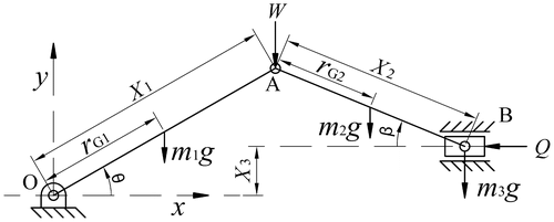
Figure 2. Slider–Crank feeding mechanism.

Figure 2. Slider–Crank feeding mechanism.

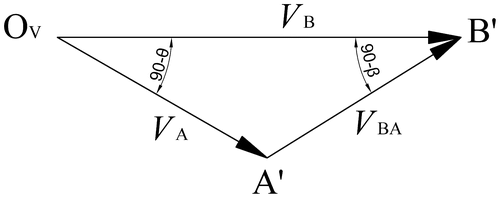
Figure 3. Velocity diagram.

Figure 3. Velocity diagram.

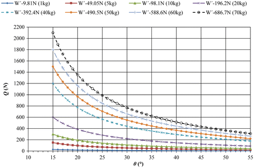
Figure 4. Qθ relationship for several constant input force W′ values.

Figure 4. Q – θ relationship for several constant input force W′ values.

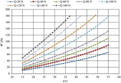
Figure 5. W′ – θ relationship for several constant output pushing force Q values.

Figure 5. W′ – θ relationship for several constant output pushing force Q values.

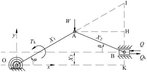
Figure 6. Kinematic diagram of slider–crank feeder mechanism with a spiral spring at point O.

Figure 6. Kinematic diagram of slider–crank feeder mechanism with a spiral spring at point O.

Figure 7. Block diagram of the control system.

Figure 7. Block diagram of the control system.

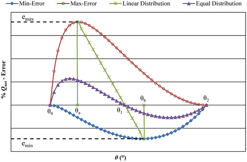
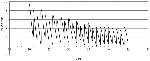
Figure 8. The relationship between the selected θ 1 and Q net Error Percentage.

Figure 8. The relationship between the selected θ 1 and Q net Error Percentage.

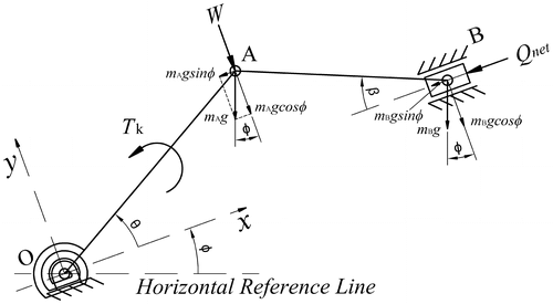
Figure 9. The slider–crank feeder mechanism inclined with an angle φ.

Figure 9. The slider–crank feeder mechanism inclined with an angle φ.

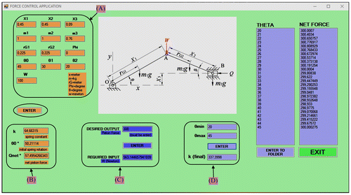
Figure 10. The user interface of force control in slider–crank feeder mechanism.

Figure 10. The user interface of force control in slider–crank feeder mechanism.

Table 1. W–input values for manual control process.

Figure 11. Error percentage – θ relationship obtained using manual control method for Q = 300 N.

Figure 11. Error percentage – θ relationship obtained using manual control method for Q = 300 N.

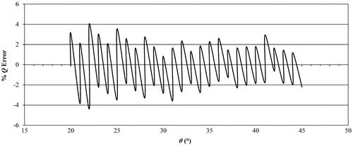
Figure 12. Error percentage – θ relationship obtained by offsetting Q net value.

Figure 12. Error percentage – θ relationship obtained by offsetting Q net value.

Table 2. The parameters used in the application of a controller.

Table 3. The parameters calculated in control application.

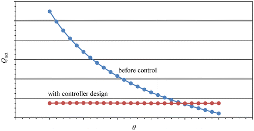
Figure 13. Variation of net pushing forces developed by a constant 100 N load and five different springs in the operation interval.
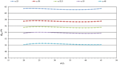
Figure 13. Variation of net pushing forces developed by a constant 100 N load and five different springs in the operation interval.

Figure 14. Variation of per cent error in the net pushing force developed by a constant 100 N load and five different springs in the operation interval.
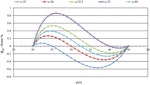
Figure 14. Variation of per cent error in the net pushing force developed by a constant 100 N load and five different springs in the operation interval.

Table 4. The equal error parameters.

Figure 15. Angle θ 1 calculated using Equal Error Distribution Method and the resulted Q net values.
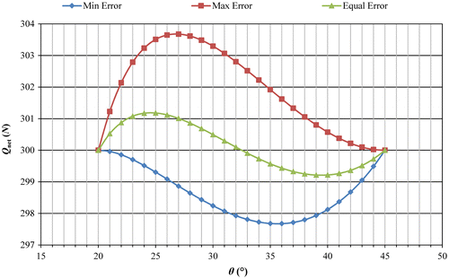
Figure 15. Angle θ 1 calculated using Equal Error Distribution Method and the resulted Q net values.
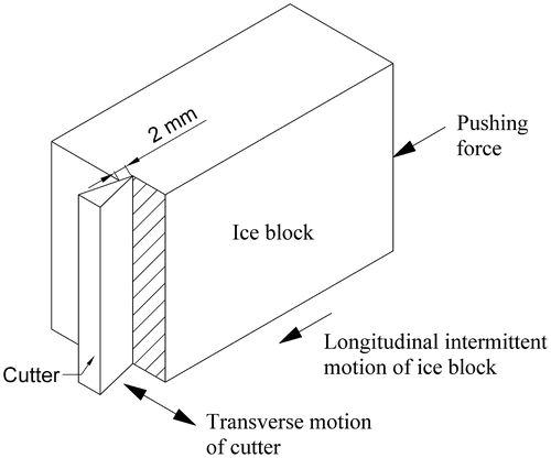
Figure 16. Piston pushing force vs. crank angle.

Figure 16. Piston pushing force vs. crank angle.

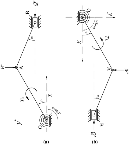
Figure 17. The slider–crank mechanism inclined (a)+90° and (b) −90°.

Figure 17. The slider–crank mechanism inclined (a)+90° and (b) −90°.

Table 5. Calculated values for the general case applications.

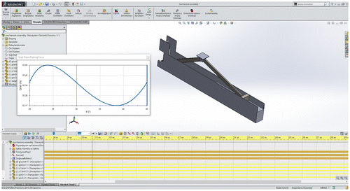
Figure 18. The slider–crank feeder mechanism simulated in SolidWorks.

Figure 18. The slider–crank feeder mechanism simulated in SolidWorks.

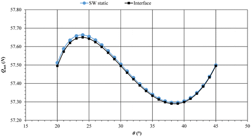
Figure 19. Comparison of Q net values obtained by SolidWorks simulations and the developed user interface.

Figure 19. Comparison of Q net values obtained by SolidWorks simulations and the developed user interface.

Reprints and Corporate Permissions

Please note: Selecting permissions does not provide access to the full text of the article, please see our help page How do I view content?

To request a reprint or corporate permissions for this article, please click on the relevant link below:

Academic Permissions

Please note: Selecting permissions does not provide access to the full text of the article, please see our help page How do I view content?

Obtain permissions instantly via Rightslink by clicking on the button below:

If you are unable to obtain permissions via Rightslink, please complete and submit this Permissions form. For more information, please visit our Permissions help page.