Figures & data
Figure 1. RSSR-SS linkage (left) with joint descriptions and (right) with displacement variables.
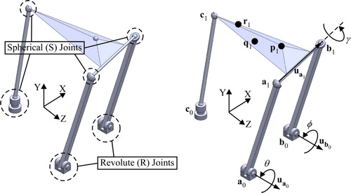
Figure 2. RSSR-SS (a) , (b)
and (c)
coupler rotations.
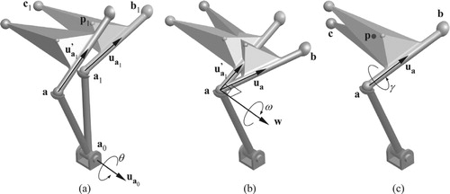
Figure 3. (a) Four-bar linkage assembly configurations and (b) branch defect.
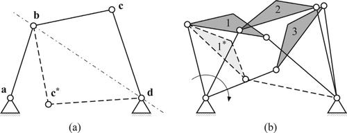
Figure 4. Order difference with four precision points (orders (a) 1-2-3-4 and (b) 1-2-4-3).
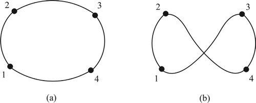
Figure 5. Four-bar linkage with circuit defect.
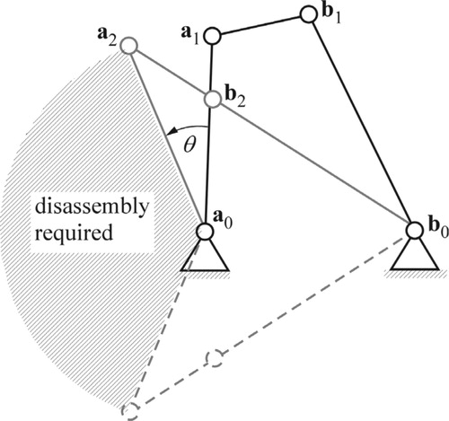
Table 1. Equation, Gradient and Hessian File Sizes (in MB for  coupler positions) in Matlab.
Figure 6. Precision positions and precision position force.
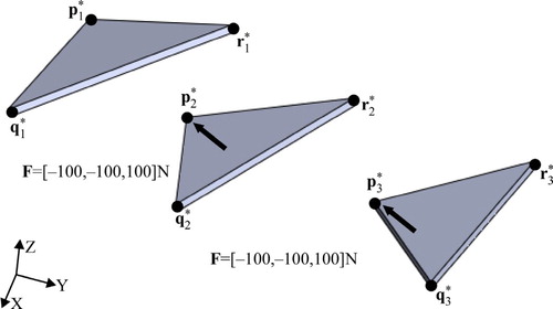
Table 2. Precision position coordinates.
Table 3. Initial and calculated RSSR-SS linkage variable values.
Table 4. Coupler position coordinates achieved by the synthesized RSSR-SS linkage.
Figure 7. Synthesized RSSR-SS linkage at (top) initial and (bottom) final achieved coupler positions.
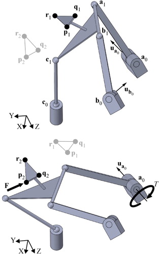
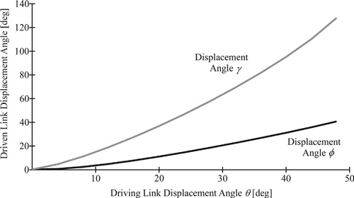
Figure 8. Driven link displacement angles (versus driving link rotation) for synthesized linkage.
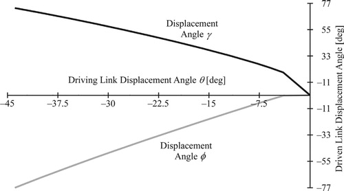
Figure 9. Synthesized RSSR-SS linkage at (top) initial and (bottom) final achieved coupler positions.
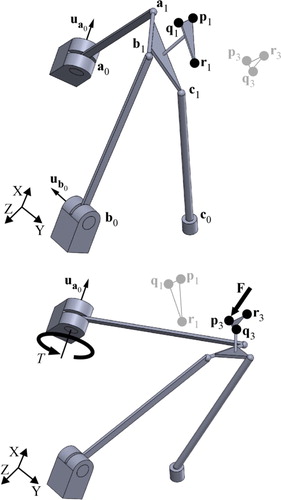
Figure 10. Driven link displacement angles (versus driving link rotation) for synthesized linkage.