Figures & data
Table 1. CAC risk factors [Citation1,Citation7,Citation10–Citation12] and PCI adverse events due to CAC [Citation5,Citation13–Citation27].
Table 2. Coronary atherectomy device comparison.
Table 3. Coronary orbital atherectomy system (OAS) mechanism of action and technique tips.
Figure 1. Diamondback 360® coronary orbital atherectomy system (OAS) Classic Crown (1.25mm). (a) OAS device features. (b) Close-up view of the OAS crown, drive shaft, nose cone, and spring tip. (c) The physics of the OAS mechanism of action.
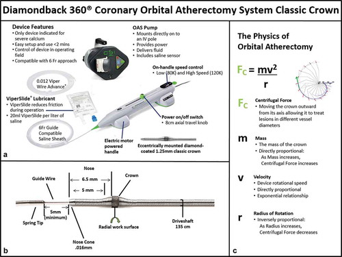
Table 4. Coronary OAS: ORBIT I and II results [Citation38,Citation45–Citation51].
Table 5. Coronary OAS treatment algorithm – best practices and optimal technique.
Figure 2. Approach to lesion preparation for severely calcified coronary lesions.
Figure 3. OCT imaging with angiographic co-registration of coronary OAS treatment. Top row is OCT imaging; bottom row is angiographic co-registration. a and a’. Baseline image of calcified coronary lesion (white arrows) pre-OAS treatment. b and b’. Post-OAS image indicating calcified plaque modification (short white arrows). c and c’. Final image showing stent expansion and apposition.
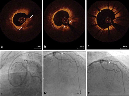
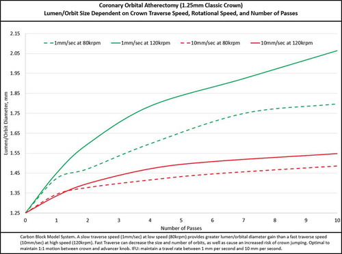
Figure 4. OAS orbit/lumen diameter dependent on crown traverse speed, rotational speed, and number of passes.