1,148
Views
0
CrossRef citations to date
0
Altmetric
Original Research

Critical analysis of in vitro stability testing of spinal implants and proposal for standardization

ORCID Icon, ORCID Icon, , ORCID Icon, , ORCID Icon, ORCID Icon & ORCID Icon show all
Pages 281-286 | Received 24 Aug 2021, Accepted 11 Mar 2022, Published online: 21 Mar 2022

Figures & data

Figure 1. The schematic drawing of the device developed for lubricity measurements. 1. compression force by spring. 2. moving force. 3. contact surface.
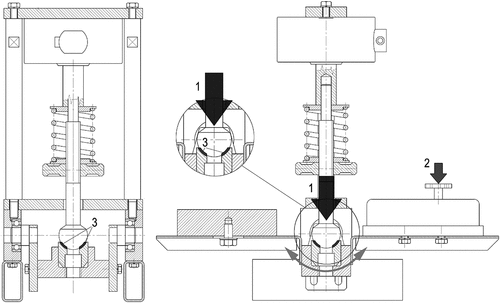
Figure 1. The schematic drawing of the device developed for lubricity measurements. 1. compression force by spring. 2. moving force. 3. contact surface.

Figure 2. The scheme of the setup of stability measurements (a) and using an Instron 8874 material testing machine (b) according to the ASTM 1798–97 (2008) standard setup.
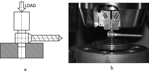
Figure 2. The scheme of the setup of stability measurements (a) and using an Instron 8874 material testing machine (b) according to the ASTM 1798–97 (2008) standard setup.
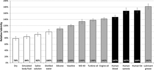
Figure 3. The calculated relative lubricity average values and standard deviation (SD) compared to distilled water. Human samples are represented in black color and the industrial lubricants in light gray. The other conditions (SBF, saline solution, dry) are plotted in white bars.

Figure 3. The calculated relative lubricity average values and standard deviation (SD) compared to distilled water. Human samples are represented in black color and the industrial lubricants in light gray. The other conditions (SBF, saline solution, dry) are plotted in white bars.

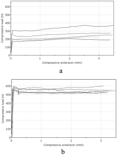
Figure 4. Perpendicular push-out force. The results of the stability measurements; force/displacement charts: a. 2-Nm tightening torque and b. 4.5-Nm tightening torque.

Figure 4. Perpendicular push-out force. The results of the stability measurements; force/displacement charts: a. 2-Nm tightening torque and b. 4.5-Nm tightening torque.