Figures & data
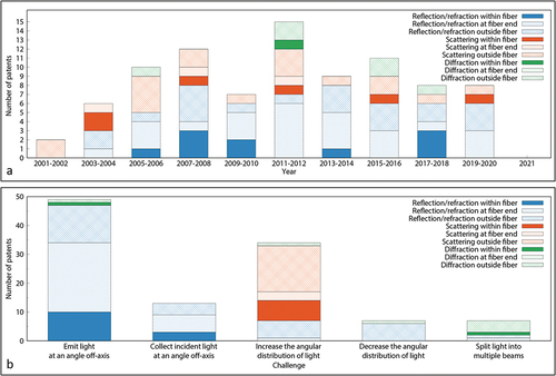
Figure 1. a Schematic representation of the patent selection method. b Distal end designs of fiber-optic medical devices that can steer light in the desired direction, categorized based on the working principle to steer light (Level 1) and the design strategy that was employed (Level 2). References are given in brackets.
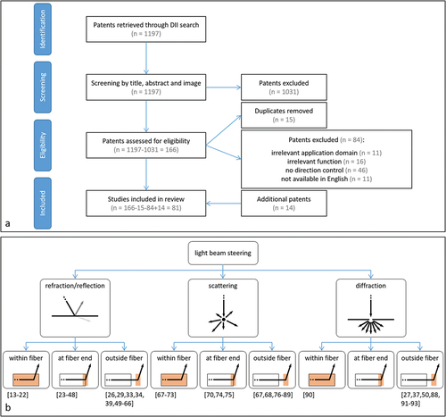
Figure 2. Distal end designs of fiber-optic medical devices to steer a light beam toward the tissue with refraction and reflection. In the design sketches, blue lines delimitate the fiber core; dashed red lines indicate the center of the light beam within the fiber; red arrows indicate the light leaving the fiber. a Bent fiber with path curved away from the central axis of the device (adapted from [Citation14]). b Twisted fibers in six-around-one configuration (adapted from [Citation20]). c Fiber with removed fiber cladding (Orange) that forms a side-facing tip (adapted from [Citation21]). d Fiber tip with slanted core end surface with reflected (bright red) and refracted (dark red) light beam (adapted from [Citation24]). e Fiber tip with cone-shaped core end surface (adapted from [Citation40]). f Fiber tip with multiple slanted surfaces in axial direction (adapted from [Citation46]). g Fiber with micro-sphere coating (pink) at core end surface (adapted from [Citation48]). h Distal tip (green) with slanted surface (pink) (adapted from [Citation49]). i Distal tip (green) with varying bevel reflecting surface (pink) (adapted from [Citation55]). j Distal tip (green) with semi-spherical lens (pink) (adapted from [Citation49]). k Fiber with prism (pink) (adapted from [Citation66]).
![Figure 2. Distal end designs of fiber-optic medical devices to steer a light beam toward the tissue with refraction and reflection. In the design sketches, blue lines delimitate the fiber core; dashed red lines indicate the center of the light beam within the fiber; red arrows indicate the light leaving the fiber. a Bent fiber with path curved away from the central axis of the device (adapted from [Citation14]). b Twisted fibers in six-around-one configuration (adapted from [Citation20]). c Fiber with removed fiber cladding (Orange) that forms a side-facing tip (adapted from [Citation21]). d Fiber tip with slanted core end surface with reflected (bright red) and refracted (dark red) light beam (adapted from [Citation24]). e Fiber tip with cone-shaped core end surface (adapted from [Citation40]). f Fiber tip with multiple slanted surfaces in axial direction (adapted from [Citation46]). g Fiber with micro-sphere coating (pink) at core end surface (adapted from [Citation48]). h Distal tip (green) with slanted surface (pink) (adapted from [Citation49]). i Distal tip (green) with varying bevel reflecting surface (pink) (adapted from [Citation55]). j Distal tip (green) with semi-spherical lens (pink) (adapted from [Citation49]). k Fiber with prism (pink) (adapted from [Citation66]).](/cms/asset/82d93dc4-398b-46b3-b3a0-3ba407228524/ierd_a_2054334_f0002_oc.jpg)
Figure 3. Distal end designs of fiber-optic medical devices to steer a light beam toward the tissue with scattering. In the design sketches, blue lines delimitate the fiber core; dashed red lines indicate the center of the light beam within the fiber; red arrows indicate the light leaving the fiber. a Fiber with scattering particles (black dots) within fiber core (adapted from [Citation69]). b Fiber with scattering particles (black dots) within cladding (Orange) (adapted from [Citation71]). c Fiber including distorted scattering regions (yellow) (adapted from [Citation73]). d Fiber tip with sphere-shaped core end surface (adapted from [Citation74]). e Fiber tip with rough, cone-shaped fiber core end surface (adapted from [Citation75]). f Diffuser tip with conical region (green) including scattering particles (black dots) (adapted from [Citation80]). g Diffuser tip (green) including scattering particles (black dots) and reflector surface (pink) (adapted from [Citation84]). h Diffuser tip with multiple reflective surfaces (green) (adapted from [Citation87]).
![Figure 3. Distal end designs of fiber-optic medical devices to steer a light beam toward the tissue with scattering. In the design sketches, blue lines delimitate the fiber core; dashed red lines indicate the center of the light beam within the fiber; red arrows indicate the light leaving the fiber. a Fiber with scattering particles (black dots) within fiber core (adapted from [Citation69]). b Fiber with scattering particles (black dots) within cladding (Orange) (adapted from [Citation71]). c Fiber including distorted scattering regions (yellow) (adapted from [Citation73]). d Fiber tip with sphere-shaped core end surface (adapted from [Citation74]). e Fiber tip with rough, cone-shaped fiber core end surface (adapted from [Citation75]). f Diffuser tip with conical region (green) including scattering particles (black dots) (adapted from [Citation80]). g Diffuser tip (green) including scattering particles (black dots) and reflector surface (pink) (adapted from [Citation84]). h Diffuser tip with multiple reflective surfaces (green) (adapted from [Citation87]).](/cms/asset/f8833c0c-0bc4-45a4-8522-d74a8674b842/ierd_a_2054334_f0003_oc.jpg)
Figure 4. Distal end designs of fiber-optic medical devices to steer a light beam toward the tissue with diffraction. In the design sketches, blue lines delimitate the fiber core; dashed red lines indicate the center of the light beam within the fiber; red arrows indicate the light leaving the fiber. a Angled grating (pink) within fiber core with reflected (bright red) and transmitted (dark red) light beam (adapted from [Citation90]). b Distal tip (green) with transmission grating (pink) (adapted from [Citation27]). c Distal tip (green) with GRIN-lens (yellow) and diffraction grating (pink) (adapted from [Citation93]).
![Figure 4. Distal end designs of fiber-optic medical devices to steer a light beam toward the tissue with diffraction. In the design sketches, blue lines delimitate the fiber core; dashed red lines indicate the center of the light beam within the fiber; red arrows indicate the light leaving the fiber. a Angled grating (pink) within fiber core with reflected (bright red) and transmitted (dark red) light beam (adapted from [Citation90]). b Distal tip (green) with transmission grating (pink) (adapted from [Citation27]). c Distal tip (green) with GRIN-lens (yellow) and diffraction grating (pink) (adapted from [Citation93]).](/cms/asset/b9d38828-24fd-41a6-bce2-c5823507fe27/ierd_a_2054334_f0004_oc.jpg)
Figure 5. a Temporal distribution of distal end designs described in relevant patents published between 2001–2021, categorized based on the working principle to steer light and the design strategy that was employed. b Distribution of distal end designs described in relevant patents over challenges met, categorized based on the working principle to steer light and the design strategy that was employed.