Figures & data
Table 1. Properties of as-received powders. Data as provided by the manufacturer.
Figure 1. SEM micrographs showing defects due to poor precursors produced from dry milling, (a) axial cross-section showing densified ZrO2 and carbon particles, (b) carbon-rich elongated void, (c) carbon-rich poorly sintered region, (d) highly densified regions with lower porosity fraction than the surrounding bulk, (e and f) lower contrast O-rich phase.
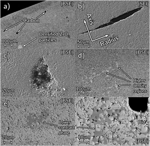
Table 2. Summary of conditions under which pellets were fabricated via RSPS.
Figure 2. RSPS pressure-temperature treatment. This sintering programme was designed to allow reaction between ZrO2 and C powder (Reaction Segment) mixture followed by a consolidation step (Sintering Segment).
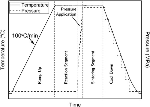
Figure 3. TEM of as-received ZrO2 powder (a) bright field image of area selected for diffraction, and (b) SADP.
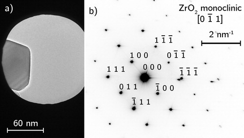
Figure 4. TEM analysis of as-received acetylene carbon black (a) selected area for diffraction, (b) indexed annular SADP, (c) high-resolution image of turbostratic graphitic layers.
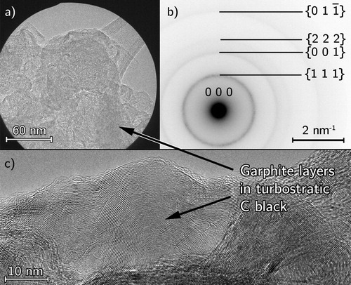
Figure 5. Secondary electron SEM images of coarse ZrO2 powder with hard agglomerates, (a) close up of an agglomerate (with insert LDA measured particle size distribution), and (b) low magnification of agglomerates.
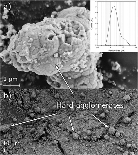
Figure 6. SEM micrograph of fine ZrO2 + C powder mixture after milling.
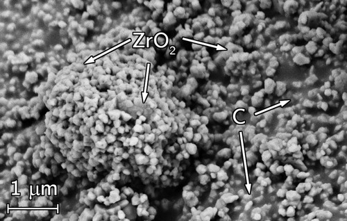
Figure 7. Gas release during RSPS for sample T03, the gas release curve has been smoothed for ease of visualisation.
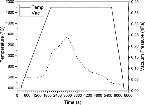
Figure 8. XRD for samples T01–T04 (a–d) and PDF reference patterns for (e) ZrC, (f) monoclinic ZrO2 and (g) tetragonal ZrO2.
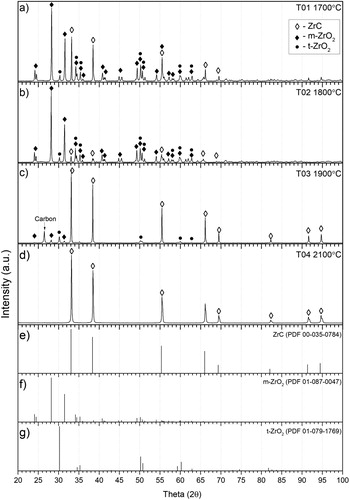
Table 3. Phase lattice parameters and wt-% obtained by Rietveld analysis for T01–T03.
Table 4. QCA for various samples reacted at increasing temperatures as well as P01 reacted without applied pressure.
Figure 9. RSPS reaction for T04 showing piston travel, vacuum pressure and applied power. The Roman numerals denote the various reaction segments given in .
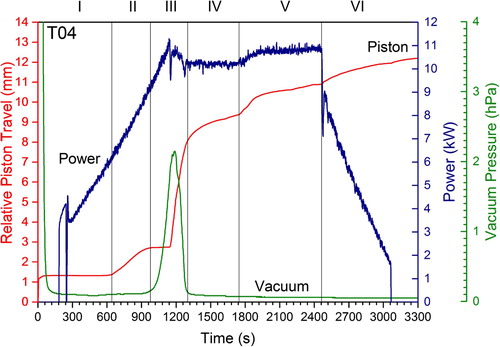
Figure 10. Compositional SEM of T04 (top left) and with overlaid EDS elemental map showing the Zr, C and O distribution thus. Phases are identified in the top-left micrograph as ZrC (bulk), O-rich ZrOC (dark grains), closed submicron pores (dark spots).
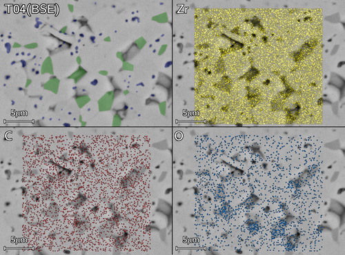
Table 5. Lattice parameters, densities and free carbon contents for all samples, ZrC theoretical density (TD) is taken as 6.59 g cm–3 [Citation18].
Figure 11. (a) Piston travel and (b) gas release during RSPS of RP samples plotted as function of time.
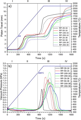
Table 6. Experimental QCA and calculated elemental ratios for all samples produced by reactive SPS at 2100°C from the heat rate and pressure set. In addition, initial compositions of the precursor powders are shown.
Figure 12. Correlation between oxygen content and bulk density for the set of heating rate and pressure samples produced by RSPS at 2100°C (Minimum Pressure = 16 MPa, Sintering Pressure = 38 MPa.)
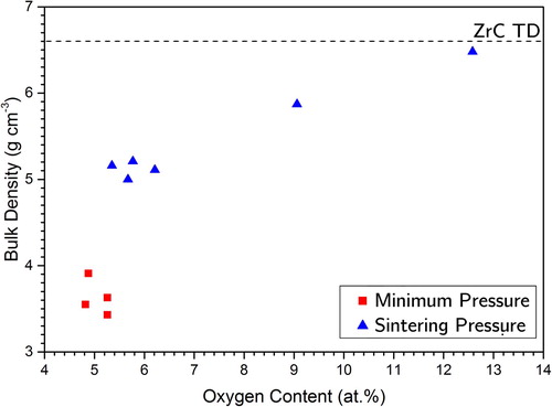
Figure 13. XRD patterns for pressure and heating rate for experiments labelled as RP-XX-XX in .
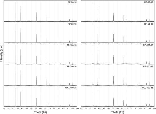
Figure 14. SEM micrographs of RP-100-38 showing free carbon between interconnected ZrOC grains (a) boundary between ground surface (appearing black from smeared carbon) and a fractured surface of primarily light contrast ZrOC grains and high magnification images of (b) smeared carbon and (c) ZrOC grains illustrating necking.

Figure 15. High magnification SEM micrograph of ZrOC grain necking from RP-200-16.
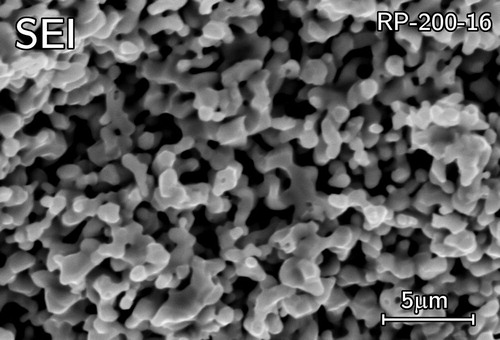
Figure 16. Mechanism of the RSPS process, (a) starting ZrO2 + C powders, (b) onset of sintering of the ZrO2 forming necks at contact points, (c) nucleation of the O-rich ZrOC phase, (d) simultaneous growth of the ZrOC and consumption of the ZrO2 phases, (e) neck formation at contact points between the ZrOC particles, (f) upon consumption of all ZrO2 the oxygen is reacted out of the ZrOC phase producing ZrC, (g) once all C is consumed ZrC is the only phase remaining and (h) is its sintering in the final phase of the RSPS.
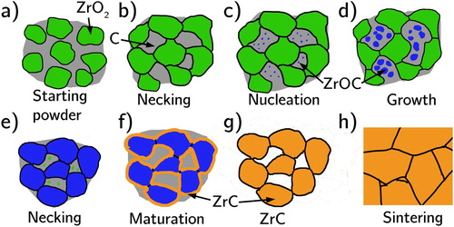
Figure 17. SEM micrographs of pressureless reacted P01 taken from mid pellet height (a) low magnification of pellet centre (b) to rim (c). A higher magnification (d) backscatter image in the rim region.
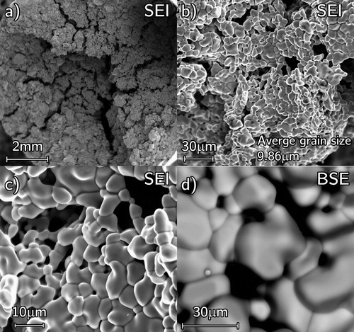
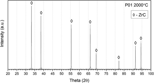
Figure 18. XRD pattern for pressureless sample P01.