Figures & data
Figure 1. Diagram of a marine electric power plant using SOFC stacks in combination with a regenerative gas turbine operating with over-expansion: 1. electric generator; 2. compressor; 3. turbine; 4. exhauster; 5. gas cooler; 6. regenerator; 7. air superheater; 8. circulation pump; 9. ejector supply of associated gas; 10. preliminary reformer; 11. built-in reformer; 12. combustor; 13 (1), 13 (2). DC-AC inverters; 14. AC-DC inverter; A. atmospheric air; G. exhaust gases; F. fuel supply (associated gas).
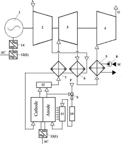
Table 1. Results of verification of the gas turbine part’s model.
Table 2. Assumptions for the SOFC stack mathematical model.
Figure 2. Efficiency of the SOFC-regenerative gas turbine with overexpansion hybrid scheme.
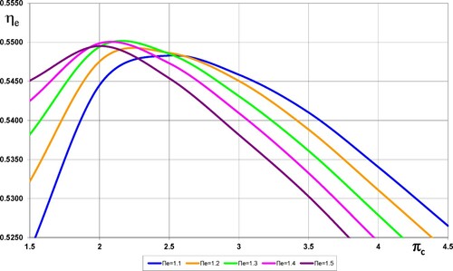
Figure 3. Gas turbine inlet temperature in a hybrid power generation system.
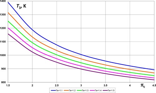
Figure 4. The total power of a hybrid scheme (kW) per 1 stack.
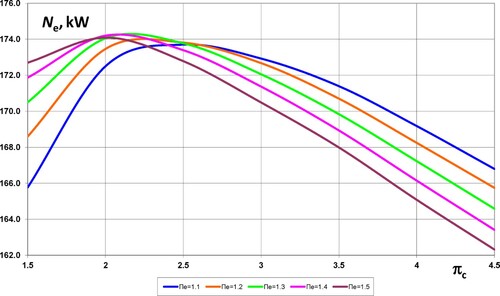
Table 3. The main parameters of a hybrid SOFC-GT system.
Figure 5. Geometry model of the combustor: (a) longitudinal combustion section; (b) combustion liner.
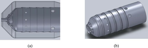
Table 4. Reactions to the fuel oxidation mechanism.
Figure 6. Experimental and calculated dependences of air flow via the ejector on air flow via the combustor: (a) – cool blow mode; (b) – hot blow mode.
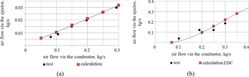
Figure 7. Velocity vector coloured by velocity magnitude, m s−1.
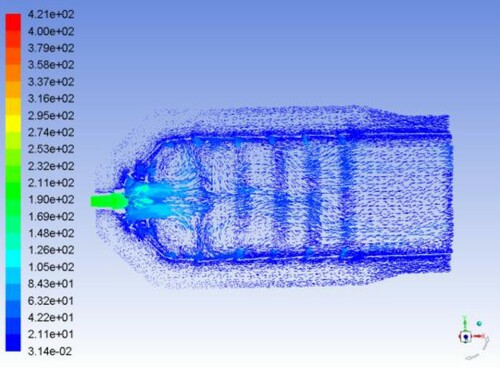
Figure 8. Contours of static temperatures, K.
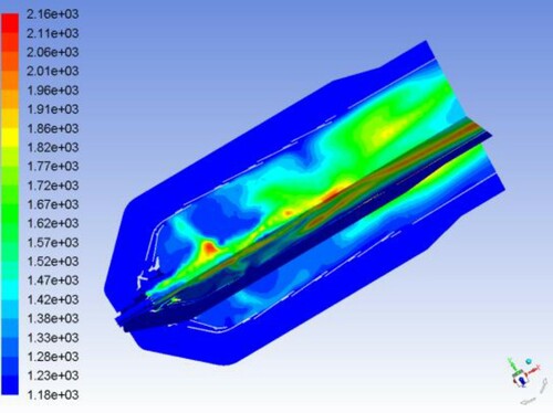
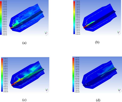
Figure 9. Contours of mass fraction of (a) H2; (b) CO; (c) CO2; (d) NO.