
Figures & data
Figure 1. Offshore application of marine bonded hoses showing different offshore platforms and marine hoses (This figure is available in colour online).
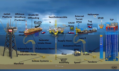
Figure 2. The extreme size of dredging hoses compared to floating hoses (Courtesy: Antal et al. Citation2012; Adapted with permission of Germa Hornsby of Continental Dunlop Oil & Marine) (This figure is available in colour online).
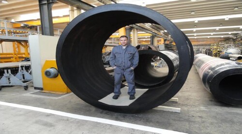
Table 1. Historical timeline on the development of marine bonded hose technologies, with founding years of manufacturers.
Figure 3. Failure and damage incidents on unbonded flexible pipes using 2002, 2010, 2018 data (Sources: Muren Citation2007; Saunders and O'Sullivan, Citation2007; Drumond et al. Citation2018; PSA Citation2018; Adapted with permission of PSA Norway & Elsevier Publishers) (This figure is available in colour online).
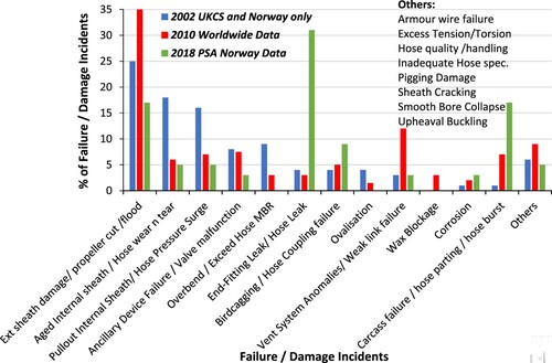
Figure 4. Hose developments by Dunlop ContiTech, showing (a) Preformed production lines (b) Conventional and preformed production jumpers (c) Water uptake line removed from Barracuda Oilfield (Brazil) for inspection, ID > 1000 mm, (d) Schematic drawing of a water intake system, (e) TauroBend preformed 3” (76 mm) 103,4 MPa (15000 psi) bonded Choke and Kill line, capable of 121°C operating temperature and more than 36 MPa collapse pressure, (f) Schematic drawing of the top of subsea blow out preventer (g) API 17 K range of offshore offloading hoses in challenging arctic sea, (h) pile driving application using a pile harmer and a hose from yoke to articulated tower (Adapted with permission of Germa Hornsby of Continental Dunlop Oil & Marine, Sina Leswal and Diana Boenning, both of Heuthig -parent media house of Kautschuk und Gummi Kunststoffe (KGK) publications, and acknowledgement from Nagy Tibor -the author of the KGK publications; Source: Nagy et al. 1998; Katona et al. Citation2009; ContiTech Citation2018, Citation2020b) (This figure is available in colour online).
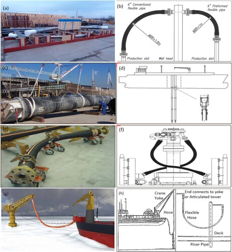
Table 2. Typical list of currently-available hose range (Courtesy: ContiTech Citation2018).
Figure 5. End fitting designs showing (a1) end fitting with built-in coupling, (a2) end-fiting with swaged couplings, (c) parts of normal DOM end fitting and (d) parts of DOM End fitting with built-in coupling (Courtesy: Dunlop ContiTech; Adapted with permission of Germa Hornsby of Continental Dunlop Oil & Marine) (This figure is available in colour online).
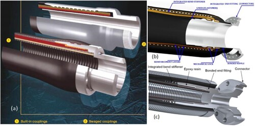
Figure 6. Dual carcass reeling hose ends showing (a) reinforced flange/ bolt indent, and (b) nippleless reinforced flange (Adapted with permission of Jonathan Petit of Trelleborg; Courtesy: Trelleborg) (This figure is available in colour online).
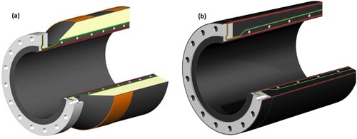
Table 3. Main components of a typical loading and discharge marine bonded hose.
Figure 7. Schematic representation of Floating hose and Submarine Hose (Courtesy: Yokohama) (This figure is available in colour online).
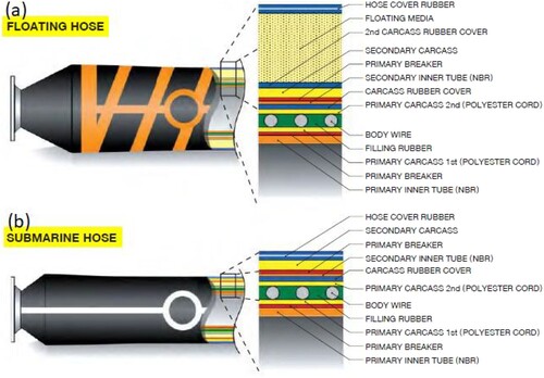
Figure 8. Hose reinforcement showing (a) hose reinforcement and elastomer materials on a floating hose, and (b) hose layers, ring stiffened reinforcement and armoured layers of dredging hose (Courtesy: (a) Elsevier Publishers & Gao Q. et al. Citation2018; (b) Shandong HOHN Group) (This figure is available in colour online).
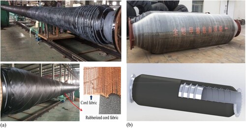
Table 4. Some manufacturers of API standard marine hoses.
Table 5. Typical hose manufacturing defects with defect rate before 2008 (Courtesy: ContiTech).
Table 6. Commonly used elastomers in bonded hoses with the rubber properties.
Table 7. Material tests recommended by OCIMF (Citation2009) standard.
Figure 9. Two hose systems showing reels, reeling hoses, marine breakaway coupling (MBC) and Hose End Valve (HEV) (This figure is available in colour online).
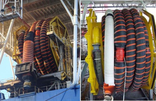
Figure 10. Marine hose showing hose coupling (MBC) on floating and reeling hose (Courtesy: Kenwell & Yokohama) (This figure is available in colour online).
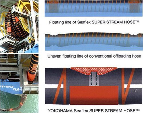
Figure 11. Pipe-laying technique called reel-lay using FPSO-mounted reeling drum and reeling hoses (Courtesy: Subsea7) (This figure is available in colour online).
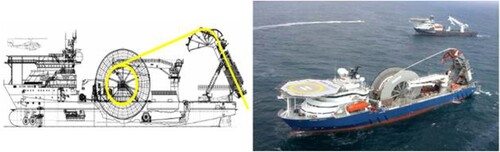
Figure 12. Bending moment vs curvature for a reeling hose system (This figure is available in colour online).
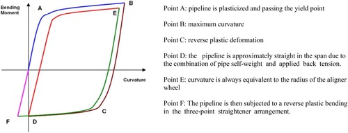
Figure 13. State-of-the-art configurations for marine hoses and marine risers (This figure is available in colour online).
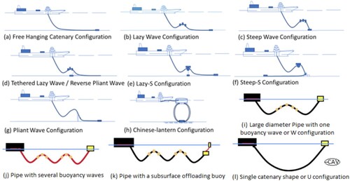
Figure 14. Typical depiction of underwater marine hoses in Lazy-S (Hose Image adapted with permission of EMSTEC, but sketch was designed by Author 1- C.V.A; Hose Courtesy: EMSTEC) (This figure is available in colour online).
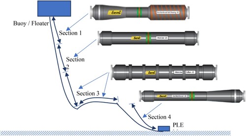
Figure 15. Depiction of waves acting upon floating buoy having marine hoses in Chinese-lantern configuration (This figure is available in colour online).
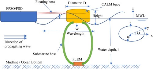
Figure 16. CALM Buoy submarine hoses in Chinese-lantern configurations for SPM showing hose bending moment (Courtesy: Stewart B. Citation2016) (This figure is available in colour online).
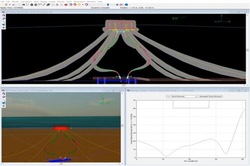
Figure 17. Hose configurations showing (a)near hose config., (b) near hose effective tension, (c) near hose normalised curvature, (d) far hose config., (b) far hose effective tension, (c) far hose normalised curvature (Courtesy: Szekely & Peixoto. Citation2018). (This figure is available in colour online).
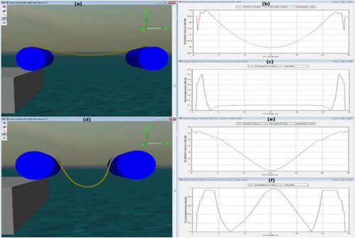
Table 8. Property requirements tests for elastomer and metallic materials according to API (Source: API 17K: 2017).
Table 9. Model tests on CALM buoy offshore hose systems.
Figure 18. Combined bending fatigue + tension using a test bench (Courtesy: Rampi et al. Citation2006) (This figure is available in colour online).
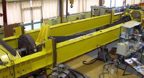
Table 10. Fatigue test results on OLL offloading marine bonded hoses (Rampi et al. Citation2006).
Table 11. Summary of the reviewed models on marine hoses covering numerical, experimental, fatigue and analytical studies.
Figure 19. Installation of floating hoses for a CALM buoy in offshore Brazil (Courtesy: BR) (This figure is available in colour online).
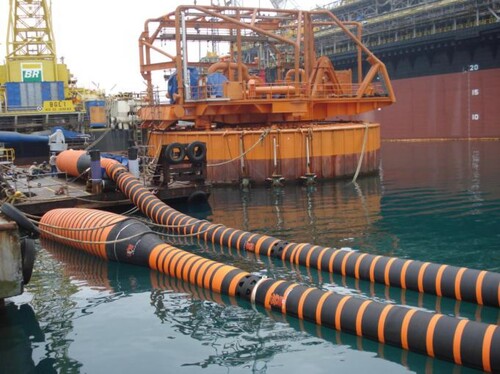
Table 12. Areas of application of marine bonded hoses for transfer, loading and offloading.
Table 13. Comparative advantages of Trelline OOL hose from technical and commercial aspects.
Figure 20. Types of hose ends with the flanges (Source: GoodYear) (This figure is available in colour online).
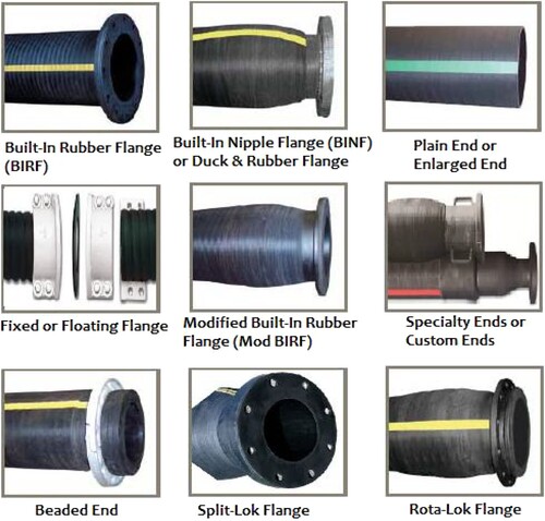
Table 14. Description of different offshore hose ends with the flanges.
Table 15. Patents on development of marine hoses and flexible pipes.
Table 16. Comparison of offloading line with multi-line solution.
Table 17. Types of hose failures assessed.
Table 18. Challenge of marine bonded hose failures and some identified causes.