
Figures & data
Figure 1. Tools and programmes of DNV Sesam used in this study.
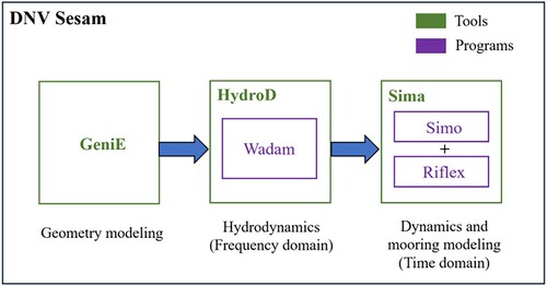
Table 1. LCoE costs of an isolated WaveEL 4.0 unit and the four farms with different array layouts. The definition of different layouts can be found in Section 2.4.2; Ringsberg et al. (Citation2020a) provided a detailed presentation of all the financial parameters and costs.
Figure 2. (a) The geometries of WaveEL 3.0 (left) and WaveEL 4.0 (right); (b) an isolated WaveEL 4.0 unit with moorings (Shao et al., Citation2023).
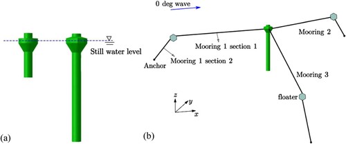
Table 2. Geometric parameters of the two WEC configurations.
Figure 3. (a) Three array layouts for WEC farms. The numbered yellow circles show the WEC units, green circles show the floaters, and blue squares show the anchors. From left to right: Hex1 (with a distance of 80 or 120 m for Hex1-80 or Hex1-120, respectively), Hex2, and StarBuoy. Examples of incident wave directions are marked with blue arrows. (b) The evolution roadmap of the three studied array layouts.
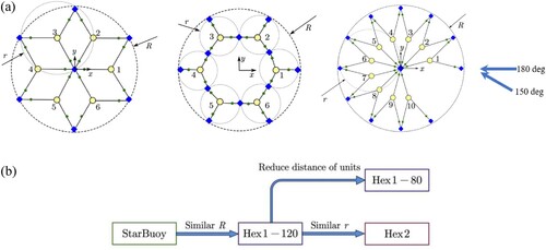
Table 3. Key parameters of the conceptual array layouts.
Table 4. Definition of three environmental conditions selected for detailed study by numerical simulations.
Figure 4. (a) Heave amplitude response per unit wave height with respect to wave period (Shao et al., Citation2023). (b) power generation of the isolated single WEC units under different environmental conditions (EC1 to 3).
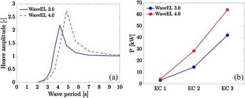
Figure 5. Normalised power absorbed by each WEC unit in the Hex1-80 layout for (a) WaveEL 3.0, (b) WaveEL 4.0, and (c) WaveEL 4.0 but normalised with the reference value of WaveEL 3.0. The incoming wave angle is 180°, which is marked with red arrows. The polar coordinate system is used here, and the unit positions are indicated in (a).
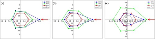
Figure 6. Normalised total power of the Hex1-80 layout with the incident wave direction of 180o.
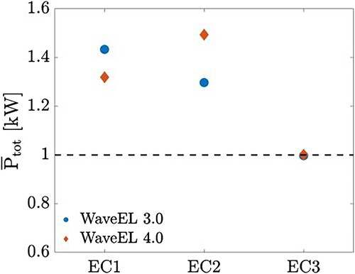
Figure 7. Normalised power output from each WEC unit in the Hex1-80 layout under EC2, using (a) WaveEL 3.0 and (b) WaveEL 4.0. The arrows indicate the incident wave directions.
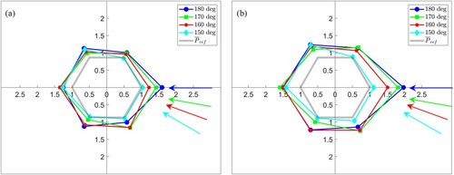
Figure 8. Normalised total power of the Hex1-80 layout with different incident wave directions under the various environmental conditions: (a) EC1, (b) EC2, and (c) EC3.
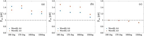
Figure 9. Normalised power generated from each WEC unit in the Hex1-120 and Hex2 layouts under EC2 with the incident wave direction of 150° for (a) WaveEL 3.0 and (b) WaveEL 4.0, and 180° for (c) WaveEL 3.0 and (d) WaveEL 4.0. Note that the polar coordinate system is used here, and the unit positions correspond to (a). The red arrows indicate the incident wave directions.
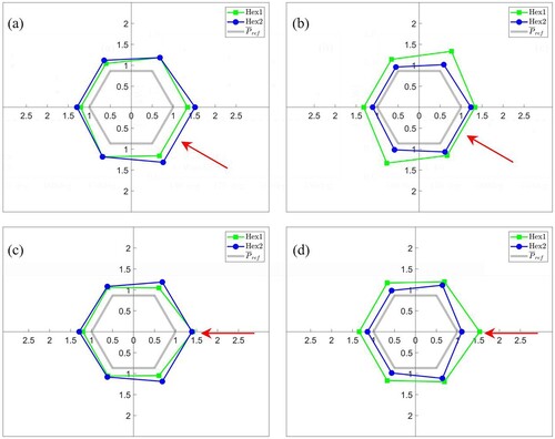
Figure 10. Normalised power generated from each WEC unit in the Hex1-120 and Hex2 layouts under EC3 with the incident wave direction of 150° for (a) WaveEL 3.0 and (b) WaveEL 4.0, and 180° for (c) WaveEL 3.0 and (d) WaveEL 4.0. Note that the polar coordinate system is used here, and the unit positions correspond to (a). The red arrows indicate the incident wave directions.
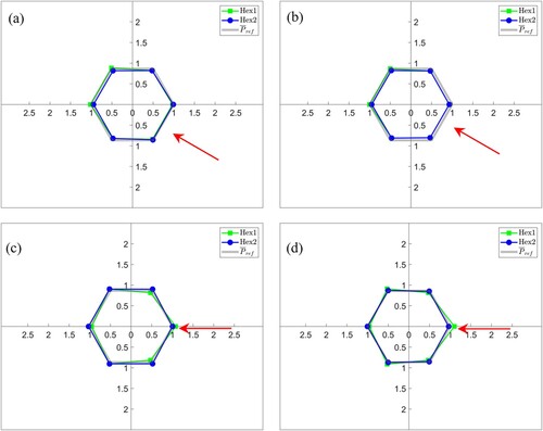
Table 5. Power interaction factors Ip [-] for Hex1-80, Hex1-120, and Hex2.
Table 6. Power interaction factors Ip [-] for StarBuoy with WaveEL 4.0 under EC2.
Table 7. Mean values of the interaction factors Ip [-] in and .
Table 8. LCoE [EUR/kWh] estimated with/without the power interaction factors Ip presented in .
Figure 11. Normalised total power from the entire layouts, Hex1-120 and Hex2, using WaveEL 3.0 and 4.0 under the different environmental conditions, EC1–3.
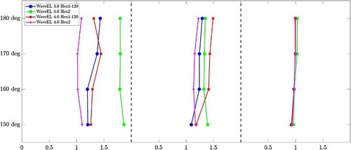
Figure 12. Normalised total power from the entire StarBuoy layout for incident wave directions of 150° to 330°, using StarBuoy with WaveEL 4.0 under EC2.
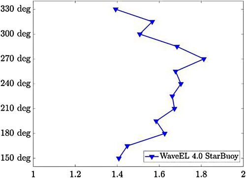
Table 9. LCoE from other studies for comparison.
Data availability statement
There is no data availability statement.