Figures & data
Figure 1. Location of the study area with extent of the Main Map 1 marked in red. Basemap data and background satellite imagery provided by © Norsk Polar Institute (http://www.npolar.no).
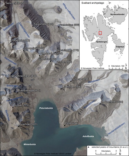
Figure 2. Geological map of the study area. The map is based on Geological Map of Svalbard 1:250,000 provided by © Norsk Polar Institute (http://geodata.npolar.no).
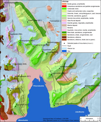
Figure 3. Examples of fluvial-flow-dominated fan surface morphology: (a) ground-based view of active and older inactive braided channels visible on the fan surface; (b) orthophoto of braided pattern of fluvial channels; (c) fluvial-flow-dominated fan with incised channel in the most proximal part and a network of active and older inactive braided channels in a more distal one. Note also that large part of this fan is vegetated.
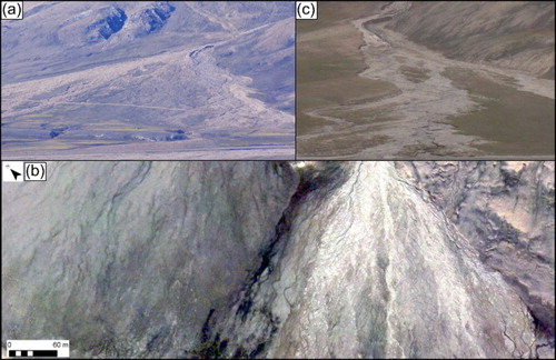
Figure 4. Examples of debris-flow-dominated fan surface morphology: (a) ground view of recent debris flow channel; (b) orthophoto of the debris-flow-dominated fan depicting a dense network of recent (‘fresh’) and older debris flow channels and lobes (c) ground view of older, partly levelled, debris flow channels.
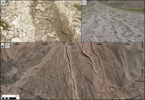
Figure 5. Examples of colluvial fan surface morphology: (a) oblique view of short and steep colluvial fans located along the fjord margin; (b) an NIR (false colour: Near Infrared – Red – Green) composite satellite image of a colluvial fan with recently modified areas emphasized by a light grey colour. The older parts of the fan are shown in green. Note also that the inactive parts of the slope between fans are vegetated and therefore highlighted in near-infrared (red in the image). Source: © Digital Globe; (c) ground-view of coalescing colluvial fans.
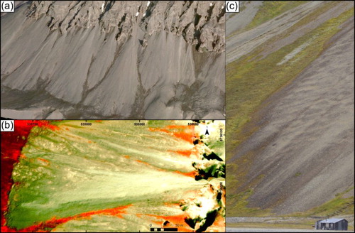
Table 1. Definitions, types and units, range of values and source of calculated morphometric properties of fans and their catchment areas.
Table 2. Outcomes of morphometric features per fan type for fans located in Petuniabukta region, Svalbard – Part I.
Table 3. Outcomes of morphometric features per fan type for fans located in Petuniabukta region, Svalbard – Part II.
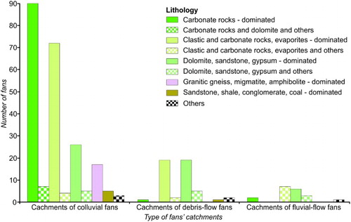
Figure 6. The lithology of the catchments of colluvial and alluvial fans in Petuniabukta.