Figures & data
Figure 1. Historic 1:2500 Ordnance Survey mapping depicting the location of the Grand Entrance on the south bank of the River Thames in London (© Crown Copyright and Database Right 2017. Ordnance Survey (Digimap Licence)).
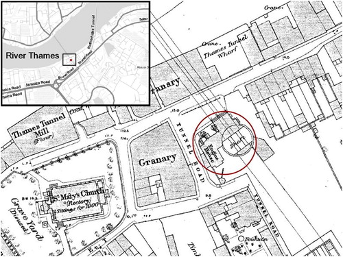
Figure 2. Artist’s impression of the Grand Entrance to the Thames Tunnel (Anonymous, Illustrated London News 1843, https://en.wikipedia.org/wiki/Thames_Tunnel).
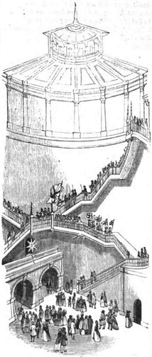
Figure 3. Examples of outputs from projects undertaken in the Grand Entrance: (a) 30 cm diameter helium balloons used to measure the height of the chamber; (b) word cloud generated from descriptive feedback; (c) interpretive sketches of students undertaking fieldwork; (d) sketches by Natalie Wyle of magnified nuances within the chamber (e.g. architectural detail, erosion and patina); (e) plane tabling and photogrammetry data collection on the floor of the chamber; (f) frame from video output of walking transects of the floor of the chamber; (g) one of the latex casts from the wall of the chamber.
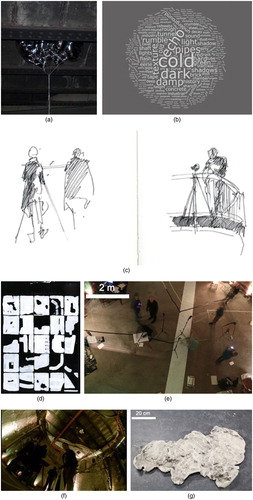
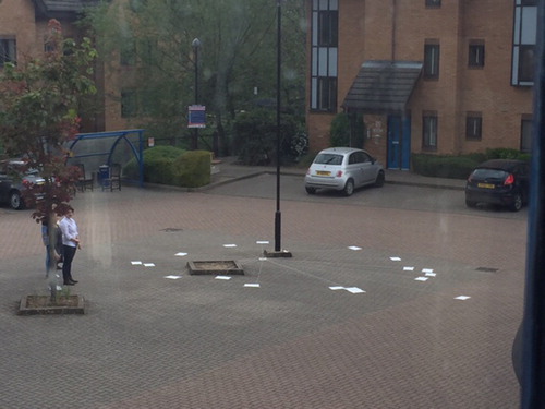
Figure 4. Output plan from the plane tabling exercise.
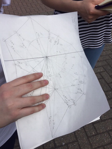
Figure 5. Creation of a larger scale plan of the Grand Entrance based upon the plane tabling output.