
Figures & data
Figure 1. Conventional AM printing techniques.
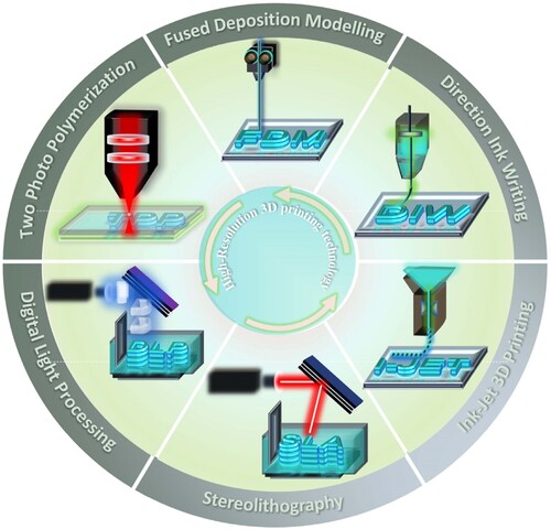
Figure 2. Historical evolution of DLP technology.
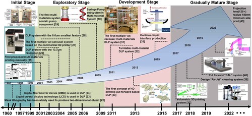
Figure 3. (a) Schematic representation of a DLP printing system. Reproduced from [Citation30], reproduced with permission from [Citation31]. (b) The high-resolution DLP printing system. (c) Micro coil array with a coil diameter of 100 µm. Scale bar: 200 µm, (d) Micro matrix. Scale bar: 200 µm. Reproduced with permission from [Citation14].
![Figure 3. (a) Schematic representation of a DLP printing system. Reproduced from [Citation30], reproduced with permission from [Citation31]. (b) The high-resolution DLP printing system. (c) Micro coil array with a coil diameter of 100 µm. Scale bar: 200 µm, (d) Micro matrix. Scale bar: 200 µm. Reproduced with permission from [Citation14].](/cms/asset/4fd552b5-2101-4653-93bd-956b340e34e3/nvpp_a_2248101_f0003_oc.jpg)
Figure 4. (a) Schematic of the ‘Top to Down’ DLP printing, (b) schematic of the ‘Bottom to Up’ DLP printing. Reproduced with permission from [Citation34], (c) the blade of ‘Top to Down’ DLP printing, reproduced with permission from [Citation33], (d–e) the structures fracture surface of ‘Top to Down’ DLP printing, (f) schematic illustration of detachment movement in ‘Bottom to Up’ DLP printing, (g–h) the structure fracture surface of ‘Bottom to Up’ DLP printing Reproduced with permission from [Citation34].
![Figure 4. (a) Schematic of the ‘Top to Down’ DLP printing, (b) schematic of the ‘Bottom to Up’ DLP printing. Reproduced with permission from [Citation34], (c) the blade of ‘Top to Down’ DLP printing, reproduced with permission from [Citation33], (d–e) the structures fracture surface of ‘Top to Down’ DLP printing, (f) schematic illustration of detachment movement in ‘Bottom to Up’ DLP printing, (g–h) the structure fracture surface of ‘Bottom to Up’ DLP printing Reproduced with permission from [Citation34].](/cms/asset/fc231137-791f-442d-9334-b1f7eff180bd/nvpp_a_2248101_f0004_oc.jpg)
Figure 5. The schematic of fundamental components of DLP systems.
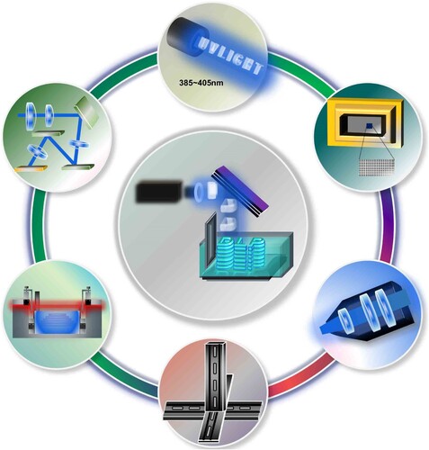
Figure 6. (a) The working mechanism of DMD-based on DLP, reproduced with permission from [Citation43]. (b) The grayscale colour representation of a DMD using hexadecimal values (0–255). (c) Micromirrors of DMD. Scale bar: 10 µm. (d) The inner hinge of the DMD Scale bar: 10 µm. (e) The torsion hinge and electrodes of micromirror arrays on the DMD chip, reproduced by permission from [Citation44]. (f) Schematic of a telecentric projection lens for digital light engines [Citation45]. (g) Schematic of a non-telecentric projection lens for digital light engines [Citation46]. (h) Illustration of the separation mechanism of DLP (button to up), reprinted with permission from [Citation47]. (i) A schematic illustrating the resin vat assembly and critical parameters, such as the dead zone, for the DLP-based 3D printing system(button to up), reprinted with permission from [Citation35].
![Figure 6. (a) The working mechanism of DMD-based on DLP, reproduced with permission from [Citation43]. (b) The grayscale colour representation of a DMD using hexadecimal values (0–255). (c) Micromirrors of DMD. Scale bar: 10 µm. (d) The inner hinge of the DMD Scale bar: 10 µm. (e) The torsion hinge and electrodes of micromirror arrays on the DMD chip, reproduced by permission from [Citation44]. (f) Schematic of a telecentric projection lens for digital light engines [Citation45]. (g) Schematic of a non-telecentric projection lens for digital light engines [Citation46]. (h) Illustration of the separation mechanism of DLP (button to up), reprinted with permission from [Citation47]. (i) A schematic illustrating the resin vat assembly and critical parameters, such as the dead zone, for the DLP-based 3D printing system(button to up), reprinted with permission from [Citation35].](/cms/asset/32bfd5c0-82ac-4373-9a22-091596516427/nvpp_a_2248101_f0006_oc.jpg)
Figure 7. (a) The experimental data of the layer thickness h with exposure time t (the dashed lines are the linear fitting of the experimental data), reproduced with permission from [Citation31]. (b) The distribution of irradiance exposure and cure depth of a UV beam, reproduced with permission from [Citation63].
![Figure 7. (a) The experimental data of the layer thickness h with exposure time t (the dashed lines are the linear fitting of the experimental data), reproduced with permission from [Citation31]. (b) The distribution of irradiance exposure and cure depth of a UV beam, reproduced with permission from [Citation63].](/cms/asset/2ec53793-7348-41a9-bec5-256e5f330909/nvpp_a_2248101_f0007_oc.jpg)
Figure 8. Selected some commercially available DLP 3D printers currently offered in the market, indicating commercial prices and printing resolution achieved
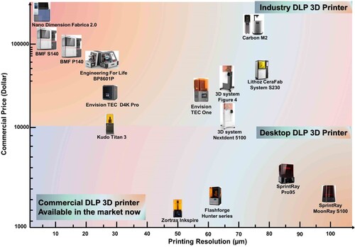
Figure 9. Free radical photopolymerisation of DLP polymer system
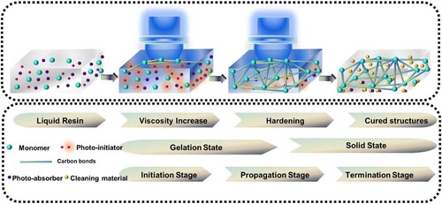
Figure 10. Summary of some common photo-initiators. (a) Cleavage of Omnirad2959 and LAP into substituent radicals following photon absorption, with molar absorptivities and cleavage products (dashed line) of the Omnirad2959 (left) and LAP (right), respectively They were reprinted with permission from [Citation127]. (b) Maple leaf structure printed by Eosin Y-based photopolymerisation of GelMA bio-ink and NIH-3T3 cell-laden printed sample at day five stained with DAPI for nuclei (blue) and phalloidin 488 for F-actin (green) Reprinted by permission from [Citation138]. (c) The structure was obtained from a photopolymer system with TPO nanoparticles Reprinted with permission from [Citation134]. (d) Normalised absorption of photo-initiators Omnirad784, CQ, and blue food dye and substrates 3D structure fabricated using a polymer containing PEGDA, Omnirad784 (left) and Rhodamine B (right). Reprinted with permission from [Citation139].
![Figure 10. Summary of some common photo-initiators. (a) Cleavage of Omnirad2959 and LAP into substituent radicals following photon absorption, with molar absorptivities and cleavage products (dashed line) of the Omnirad2959 (left) and LAP (right), respectively They were reprinted with permission from [Citation127]. (b) Maple leaf structure printed by Eosin Y-based photopolymerisation of GelMA bio-ink and NIH-3T3 cell-laden printed sample at day five stained with DAPI for nuclei (blue) and phalloidin 488 for F-actin (green) Reprinted by permission from [Citation138]. (c) The structure was obtained from a photopolymer system with TPO nanoparticles Reprinted with permission from [Citation134]. (d) Normalised absorption of photo-initiators Omnirad784, CQ, and blue food dye and substrates 3D structure fabricated using a polymer containing PEGDA, Omnirad784 (left) and Rhodamine B (right). Reprinted with permission from [Citation139].](/cms/asset/24a4f5b1-6551-4fe2-aa06-67e1da42a5ce/nvpp_a_2248101_f0010_oc.jpg)
Figure 11. The process parameters of DLP.
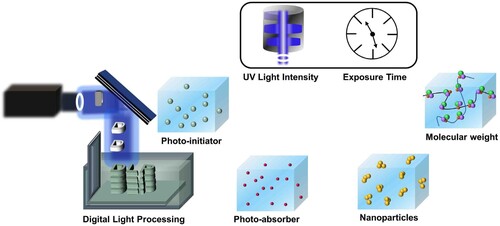
Figure 12. 3D-printed microfluidic chips based on DLP technology. (a) Schematics of the multi-material DLP printer and the fabrication process proposed for a hydrogel-based microfluidic chip. (b) Microfluidic chips are fabricated with different patterns, reprinted by permission from [Citation213]. (c) The homemade DLP 3D printer. (d) Fabrication of the channel roof using the aux platform and the corresponding grayscale mask image. (e) Fabrication result of the microfluidic valve. Reprinted by permission from [Citation213].
![Figure 12. 3D-printed microfluidic chips based on DLP technology. (a) Schematics of the multi-material DLP printer and the fabrication process proposed for a hydrogel-based microfluidic chip. (b) Microfluidic chips are fabricated with different patterns, reprinted by permission from [Citation213]. (c) The homemade DLP 3D printer. (d) Fabrication of the channel roof using the aux platform and the corresponding grayscale mask image. (e) Fabrication result of the microfluidic valve. Reprinted by permission from [Citation213].](/cms/asset/447b7969-08d8-4dc7-8726-bed260181fef/nvpp_a_2248101_f0012_oc.jpg)
Figure 13. (a) Schematic illustration of the PµSL system, (b) Micro-lattice unit cell structure, (c) Porous structure with tetrakaidecahedron unit cell architecture Reproduced with permission from [Citation4].
![Figure 13. (a) Schematic illustration of the PµSL system, (b) Micro-lattice unit cell structure, (c) Porous structure with tetrakaidecahedron unit cell architecture Reproduced with permission from [Citation4].](/cms/asset/3bab9a49-8c59-4668-9173-db81b432445d/nvpp_a_2248101_f0013_oc.jpg)
Figure 14. (a) Large-scale mask projection by moving projectors, reproduced from [Citation227]. (b) Large-scale printing projection by moving platforms. (c) Prototype of a delta DLP 3D printer, reproduced from [Citation228]. (d) The Delta mechanism to realise large-scale print, reproduced from [Citation229]. (e) The large-area DLP printing system. (f) Optical microscope images of bulk hierarchical lattice material with a network of hierarchical stretch-dominated octet unit cells. (g) Scanning electron micrographs of the hierarchical structure cross-section of multiscale metamaterial unit cell, reproduced by permission from [Citation230].
![Figure 14. (a) Large-scale mask projection by moving projectors, reproduced from [Citation227]. (b) Large-scale printing projection by moving platforms. (c) Prototype of a delta DLP 3D printer, reproduced from [Citation228]. (d) The Delta mechanism to realise large-scale print, reproduced from [Citation229]. (e) The large-area DLP printing system. (f) Optical microscope images of bulk hierarchical lattice material with a network of hierarchical stretch-dominated octet unit cells. (g) Scanning electron micrographs of the hierarchical structure cross-section of multiscale metamaterial unit cell, reproduced by permission from [Citation230].](/cms/asset/993e9661-9a0a-42ef-93b1-2f3dda8537d0/nvpp_a_2248101_f0014_oc.jpg)
Figure 15. Multi-material printing system based on the DLP technology. (a) The schematic of multi-material printing based on the air jet cleaning system and printing structures Reproduced with permission from [Citation15]. (b) Schematic illustration of the multi-materials printing based on pump system, reproduced permission from [Citation234]. (c) Schematic illustration of the multi-materials printing based on microfluidic ship system, reproduced with permission from [Citation25]. (d) Schematic illustration of the multi-materials printing based on the magnetic printing system, reproduced from [Citation235]. (e) Schematic illustration of the multi-materials printing based on the electrically assisted 3D printing device, reproduced by permission from [Citation236].
![Figure 15. Multi-material printing system based on the DLP technology. (a) The schematic of multi-material printing based on the air jet cleaning system and printing structures Reproduced with permission from [Citation15]. (b) Schematic illustration of the multi-materials printing based on pump system, reproduced permission from [Citation234]. (c) Schematic illustration of the multi-materials printing based on microfluidic ship system, reproduced with permission from [Citation25]. (d) Schematic illustration of the multi-materials printing based on the magnetic printing system, reproduced from [Citation235]. (e) Schematic illustration of the multi-materials printing based on the electrically assisted 3D printing device, reproduced by permission from [Citation236].](/cms/asset/20c36094-3428-49fd-9490-c8989a092c52/nvpp_a_2248101_f0015_oc.jpg)
Figure 16. High-speed printing system based on the DLP technology. (a) Rendered illustration of the printing zone and associated photoinduced reaction pathways of the DCPI: (i) spherical cage with the free-floating ball, 8 mm diameters, (ii) anatomical model derived from the Manix CTA dataset, 30 mm in width, reprinted with permission from [Citation239]. (b) Holographic volumetric 3D fabrication system schematic and example structures, repeated with permission from [Citation23]. (c) Underlying computed axial lithography technology concept, repeated by permission from [Citation26]. (d) Overview of the volumetric bioprinting process. (e) Schematic of tomographic projections used to print the human auricle model, repeated with permission from [Citation27]. (f) Scheme of a 3D printed part emerging from the HARP 3D printer and rigid polyurethane acrylate lattice printed in less than 3 h (vertical print rate, 120 µm/s; optical resolution, 250 µm), repeated by permission from [Citation28].
![Figure 16. High-speed printing system based on the DLP technology. (a) Rendered illustration of the printing zone and associated photoinduced reaction pathways of the DCPI: (i) spherical cage with the free-floating ball, 8 mm diameters, (ii) anatomical model derived from the Manix CTA dataset, 30 mm in width, reprinted with permission from [Citation239]. (b) Holographic volumetric 3D fabrication system schematic and example structures, repeated with permission from [Citation23]. (c) Underlying computed axial lithography technology concept, repeated by permission from [Citation26]. (d) Overview of the volumetric bioprinting process. (e) Schematic of tomographic projections used to print the human auricle model, repeated with permission from [Citation27]. (f) Scheme of a 3D printed part emerging from the HARP 3D printer and rigid polyurethane acrylate lattice printed in less than 3 h (vertical print rate, 120 µm/s; optical resolution, 250 µm), repeated by permission from [Citation28].](/cms/asset/440e5cc5-35e3-41d5-8a87-22f0da12497f/nvpp_a_2248101_f0016_oc.jpg)
Data availability statement
There is no data set associated with this paper.