
Figures & data
Figure 1. Bionic prototype and design process: (a) Crossed-lamellar structure of conch shell, (b) SEM micrographs and particle size distributions of the powders, (c) Schematic of the LDED process, (d) Schematic diagram of BHM forming.
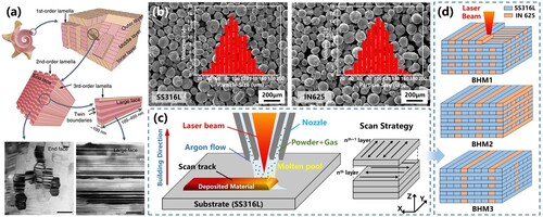
Table 1. The main chemical compositions of SS316L and IN625.
Table 2. Process parameters selected for the manufacture of BHM samples.
Figure 2. (a) Spatial characteristics of BHM sample with different material deposition distributions in different view planes; (b–c) Microstructure of the BHM sample in the X-Y; (d) The morphology of the BHM sample in the X-Z; (e–f) Zoomed image of the selected region from (d); (g) Dendrites can extend through the melt pool boundary in the Y-Z plane; (h–i) Common crystalline forms in BHM samples: dendritic and equiaxed crystals.
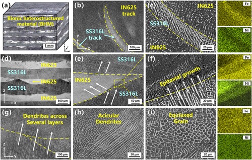
Figure 3. Morphology and chemical analysis of BHM: (a) IN625/SS316L interface; (b) SS316L/ IN625 interface.
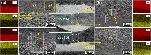
Table 3. Quantitative analysis results for the measurement points (at%).
Figure 4. Formation mechanism of the planar transition layer at the IN625/SS316L interface.
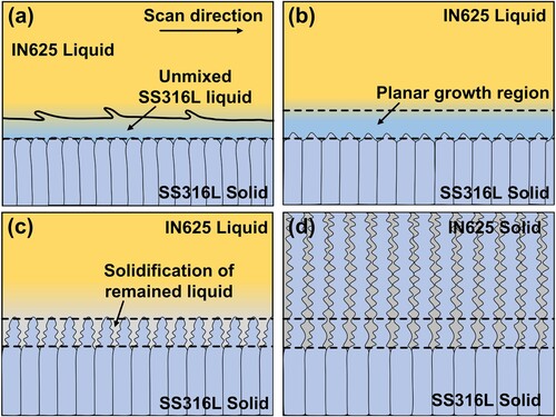
Figure 5. Crystallographic analysis of BHM sample: (a) IPF color map; (b) grain size statistical diagram; (c) pole figure map; (d) Schmidt factor distribution.
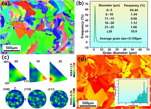
Figure 6. SEM images and EDS mapping of cracks in BHM samples: (a) solidification cracks; (b) segregation cracks; (c) ductile dip cracking; (d) IPF and KAM diagrams for ductile dip cracking.
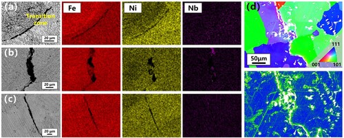
Figure 7. (a) Thermodynamic phase diagrams of (a) SS316L, (b) IN625 and (c) cracked areas; (d) X-ray diffractograms.
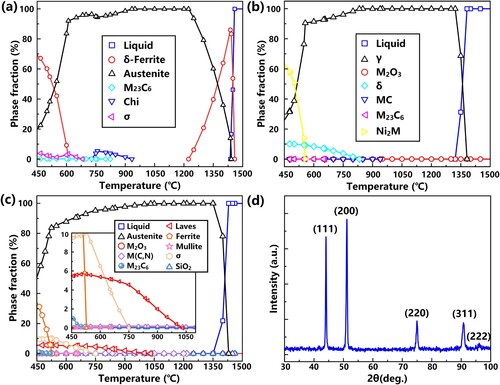
Figure 8. Indentation morphology and Vickers hardness distribution of BHM specimens along the construction direction.
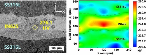
Figure 9. (a) Engineering stress-strain curves of SS316L, IN625 and BHM samples; (b) The strength level of the BHM2 sample is compared to the calculated values from ROM; (c) Comparison of UTS and EL of BHM samples with other stainless steels, nickel-based superalloys and stainless steel/nickel-based superalloy heterogeneous metal components treated by different AM processes.
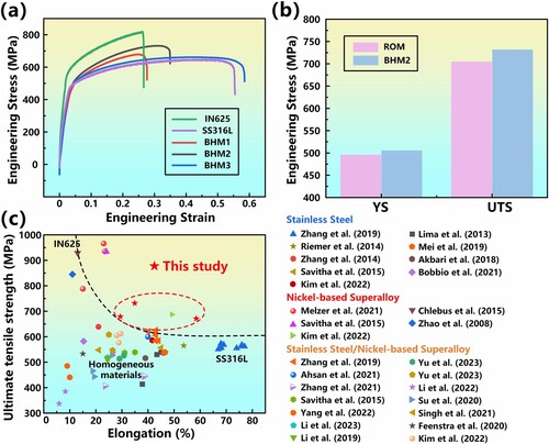
Table 4. Mechanical properties of LDED-produced SS316L-IN625 BHMs.
Figure 10. (a) LUR curve of BHM2 sample; (b) Different stresses are defined within the unloading-reloading hysteresis loop; (c) Close-up view of the first and last cycle of the hysteresis loop in the LUR curve of BHM2 sample; (d) The relationship between the measured HDI stress and true plastic strain.
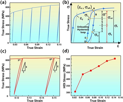
Table 5. the σr and σu values for the six LUR cycles.
Figure 11. (a) Surface slip traces at different locations; (b) Strain distribution maps in different stage monitored by DIC.
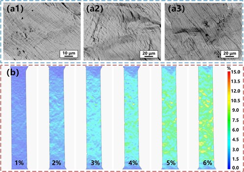
Figure 12. (a) Microstructure and elemental distribution of BHM samples after tensile stretching; (b) EBSD analysis of BHM samples after tensile stretching; (c) Fracture mechanism of BHM samples.
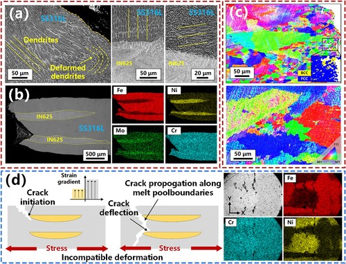
Figure 13. Deformation process of BHM in different stages [Citation62].
![Figure 13. Deformation process of BHM in different stages [Citation62].](/cms/asset/c38b967a-eed9-46b7-b091-3dfd5953cc87/nvpp_a_2266640_f0013_oc.jpg)
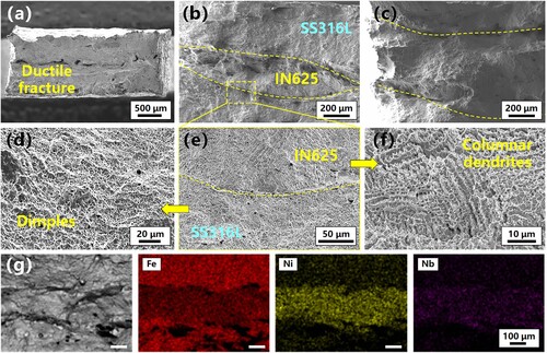
Figure 14. Tensile fracture morphology of BHM specimens. (a) Overview of the fracture surface; (b–c) Magnification micrographs of fracture surfaces; (d) SS316L side; (e) IN625/SS316L interface; (f) IN625 side; (g) EDS mapping of fracture surfaces.
Data availability statement
Data will be available upon request.