
Figures & data
Figure 1. Structures of investigated pentafluorostilbene derivatives.
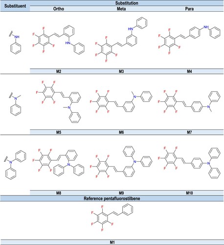
Figure 2. 3D printing models employed for DLP technology: (a) study of the resolution of the prepared resins, (b) DMA measurements, (c) TGA measurements.
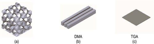
Figure 3. Absorption spectra of 1,2,3,4,5- pentafluoro-6-[(E)-styryl]benzene derivatives.
![Figure 3. Absorption spectra of 1,2,3,4,5- pentafluoro-6-[(E)-styryl]benzene derivatives.](/cms/asset/8d6b50d2-ffb9-4dae-aab1-71dad8511b42/nvpp_a_2301030_f0003_oc.jpg)
Table 1. Spectroscopic characterisation of 1,2,3,4,5-pentafluoro-6-[(E)-styryl]benzene derivatives.
Table 2. Electrochemical and thermodynamic properties of 1,2,3,4,5-pentafluoro-6-[(E)-styryl]benzene derivatives.
Figure 4. FT-IR spectrum changes for CADE epoxy monomer-based composition during cationic photopolymerisation under 365 nm UV-LED irradiation, employing IOD + M10 (1.0/0.1% w/w) initiator system.
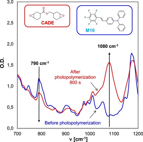
Figure 5. Kinetic profiles obtained during the cationic photopolymerisation of the epoxy monomer CADE for two-component systems consisted of the IOD iodonium salt and the appropriate 1,2,3,4,5-pentafluoro-6-[(E)-styryl]benzene derivative (1.0/0.1% w/w) during irradiation with a UV-LED emitting a wavelength of 365 nm.
![Figure 5. Kinetic profiles obtained during the cationic photopolymerisation of the epoxy monomer CADE for two-component systems consisted of the IOD iodonium salt and the appropriate 1,2,3,4,5-pentafluoro-6-[(E)-styryl]benzene derivative (1.0/0.1% w/w) during irradiation with a UV-LED emitting a wavelength of 365 nm.](/cms/asset/3d4b4192-7de7-42c5-be86-9e96443db186/nvpp_a_2301030_f0005_oc.jpg)
Table 3. The obtained conversion rates of CADE epoxy monomer during the cationic photopolymerisation process applying light sources in the UV-Vis range.
Table 4. The obtained values of induction time and kinetic curve slope during the process of cationic photopolymerisation initiated by UV- and Vis-LED light sources.
Figure 6. Effect of the amine group character present in the photosensitiser structure on the degree of CADE monomer conversion (light source LED@365 nm).
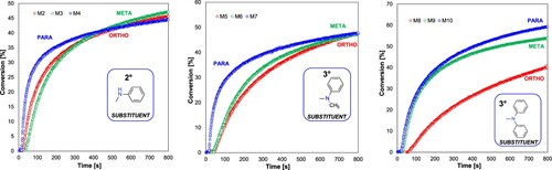
Figure 7. Influence of the substitution location of the amino group in the photosensitiser on the conversion rate of the CADE monomer (light source LED@365 nm).
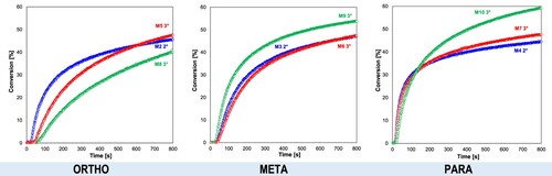
Figure 8. Photosensitisers exhibiting the highest photocatalytic activity.
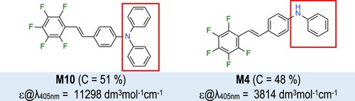
Figure 9. Changes in the FT-IR spectrum for an acrylate monomer-based TMPTA composition during radical photopolymerisation under 365 nm UV-LED irradiation, employing the IOD + M10 (1/0.1% w/w) initiator system.
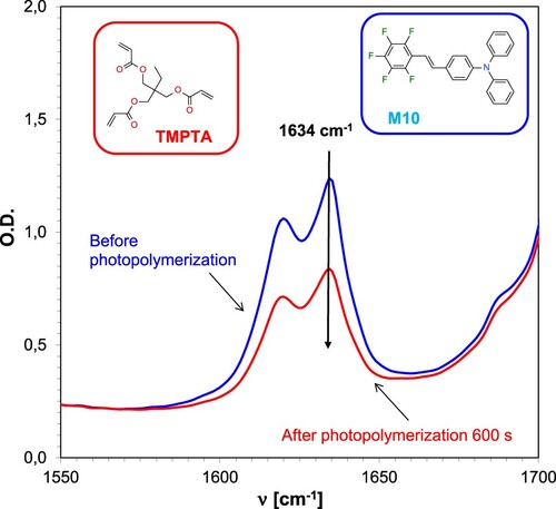
Figure 10. Kinetic profiles achieved during the progress of radical photopolymerisation of acrylate monomer TMPTA for two-component systems consisting of the IOD iodonium salt and the corresponding 1,2,3,4,5-pentafluoro-6-[(E)-styryl]benzene derivative (1.0/0.1% w/w) during irradiation with a UV-LED emitting a wavelength of 365 nm.
![Figure 10. Kinetic profiles achieved during the progress of radical photopolymerisation of acrylate monomer TMPTA for two-component systems consisting of the IOD iodonium salt and the corresponding 1,2,3,4,5-pentafluoro-6-[(E)-styryl]benzene derivative (1.0/0.1% w/w) during irradiation with a UV-LED emitting a wavelength of 365 nm.](/cms/asset/cf46a3a3-e8d1-41e3-a535-196ceae92945/nvpp_a_2301030_f0010_oc.jpg)
Table 5. The obtained conversion rates of acrylate monomer TMPTA, the values of the induction time and the slope of the kinetic curve during the progress of radical photopolymerisation initiated by UV- and Vis-LED light sources.
Figure 11. Changes in the FT-IR spectrum for resins based on CADE epoxy monomer and TMPTA acrylate monomer during hybrid photopolymerisation under 365 nm UV-LED irradiation using IOD + M9 (1.0/0.1% w/w) initiator system.
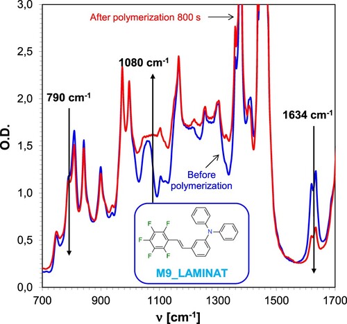
Figure 12. Kinetic profiles obtained during the photopolymerisation process of the hybrid acrylate monomer TMPTA and the epoxy monomer CADE for the two-component system consisting of the iodonium salt IOD/M10 (1.0/0.1% w/w) during irradiation with a UV-LED emitting a wavelength of 365 nm.
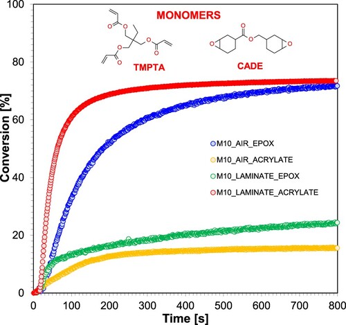
Table 6. The obtained conversion rates of acrylate monomer TMPTA and epoxy monomer CADE during the progress of hybrid photopolymerisation initiated by UV-LED light source.
Table 7. Formulation of photo-curable polymerising resins by radical mechanism.
Figure 13. Determination of printing characteristics for radical resins (1-6).
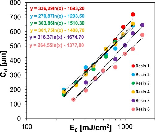
Table 8. 3D printing conditions and determined parameters for resins 1–6.
Table 9. Formulation of radical resins 2a–2e.
Figure 14. Kinetic profiles achieved during radical photopolymerisation of 2a-2e resins applying LED@405 nm light source.
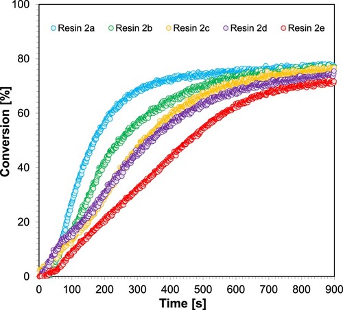
Table 10. The obtained conversion rates of acrylate monomers, the values of the induction time and the slope of the kinetic curve during the progress of hybrid photopolymerisation initiated by Vis-LED light source (LED@405 nm).
Table 11. Formulation of radical resin 2a and resin 7.
Figure 15. Determination of printing characteristics for resin 2 and resin 7.
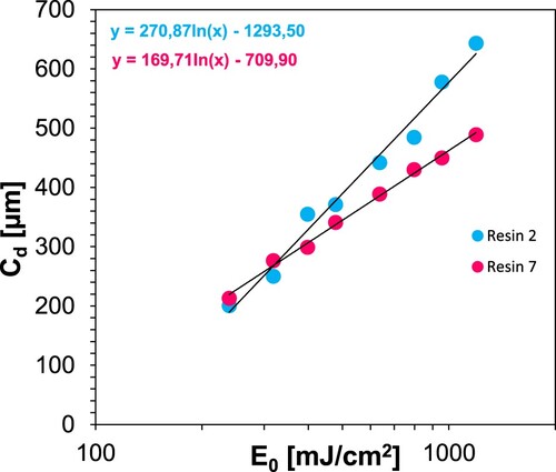
Table 12. 3D printing conditions and determined parameters for resins 2 and 7 (resin 2 + 10% ZnO).
Figure 16. Photographs of the print obtained with resin 2 using DLP technology; images taken on an optical microscope and camera; images taken under visible light and with a UV flashlight.
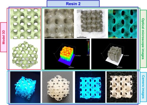
Figure 17. Photographs of the print obtained with resin 7 using DLP technology; images taken on an optical microscope and camera; images taken under visible light and with a UV flashlight.
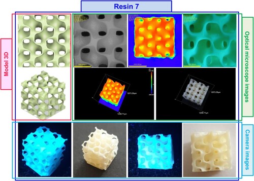
Figure 18. Photographs of a print obtained with resin 2 using DLP technology; images obtained on a scanning electron microscope.
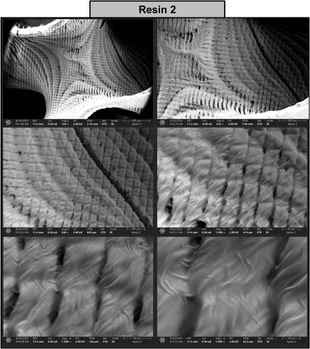
Figure 19. Photographs of a print obtained with resin 7 using DLP technology; images obtained on a scanning electron microscope.
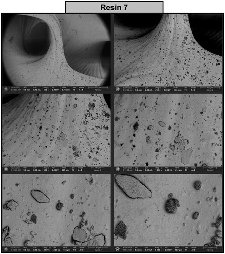
Figure 20. SEM-EDS analysis of (a) the resin 2 print, (b) the resin 7 print.
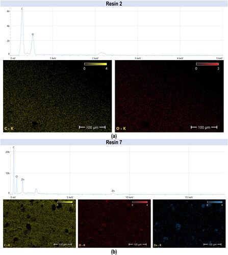
Figure 21. Dynamical mechanical analysis (DMA) analysis showing storage and loss moduli, and loss factor as a function of temperature for resin 2 (without nanoparticles) and resin 7 (with nanoparticles).
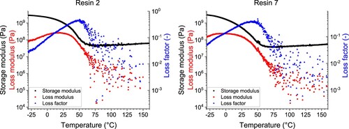
Table 13. 3D printing conditions and determined parameters for resins 1–7. Glassy at −25, rubbery at +120.
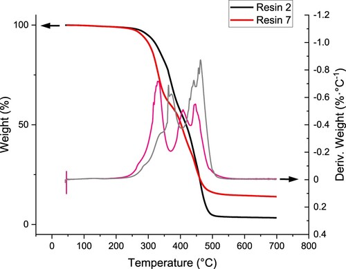
Figure 22. Thermogravimetric analysis (TGA) and differential thermogravimetric analysis (DTGA) show the relative weight change and its derivative with temperature up to 700°C.
Supplemental Material
Download MS Word (6.2 MB)Data availability statement
The data that support the findings of this study are openly available in Mendeley Data at https://data.mendeley.com/datasets/52m89r83df/1.