
Figures & data
Figure 1. Test specimen Type A (No. of grid lines = 1).
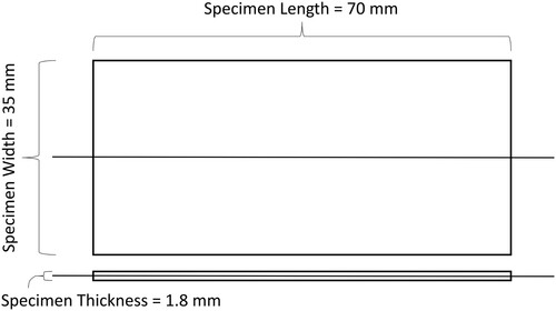
Figure 2. Test specimen Type B (No. of grid lines = 38).
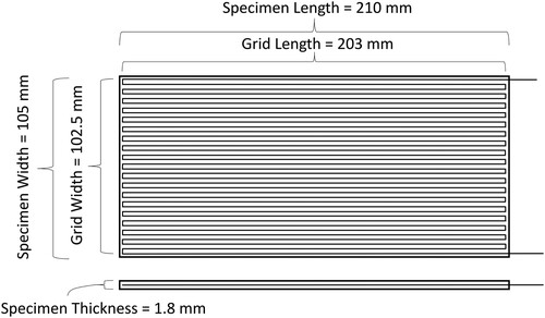
Table 1. Global additive manufacturing parameters.
Table 2. Processing parameters of continuous carbon fiber and continuous copper wire.
Figure 3. Flexural fixture for Type A specimen.
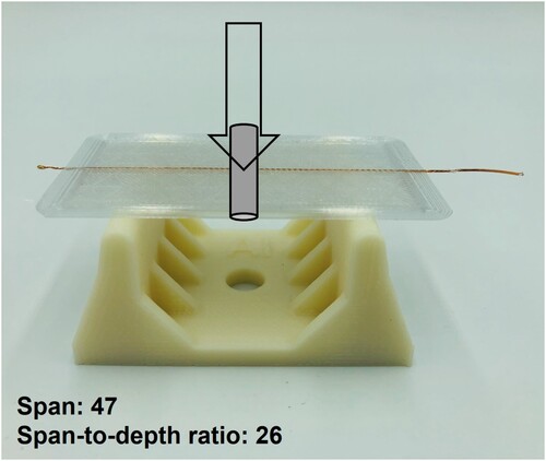
Figure 4. Flexural fixture for Type B specimen.
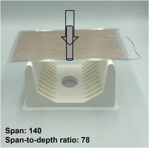
Figure 5. Additive manufacturing of Type B specimen with (a) continuous copper wire and (b) continuous carbon fiber, and (c) the end-use specimens.
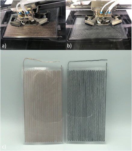
Figure 6. Self-sensing capability of Type A specimen embedded with CCW.
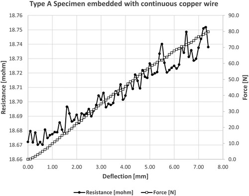
Figure 7. Self-sensing capability of Type B specimen embedded with CCW.
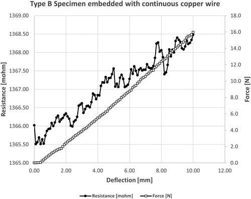
Figure 8. Self-sensing capability of Type A specimen embedded with CCF.
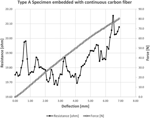
Figure 9. Self-sensing capability of Type B specimen embedded with CCF.
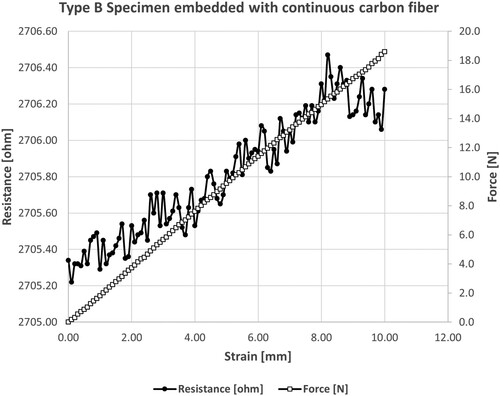
Figure 10. Linear regression of fractional change in electrical resistance as a function of force and deflection for Type A and Type B specimens. (a)Type A: CCW (b)Type B: CCW (c)Type A: CCF (d)Type B: CCF
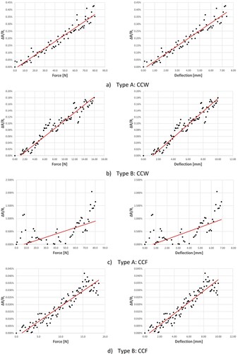
Figure 11. Flexural stress in the outer surface at midpoint as a function of flexural strain.
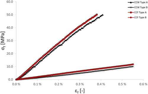
Table 3. Piezoelectric properties of the test specimens based on statistical evidence.
Data availability statement
The data that support the outcomes of this study are available from the corresponding author upon reasonable request.