
Figures & data
Figure 1. Scheme of the lithography metal additive manufacturing process.
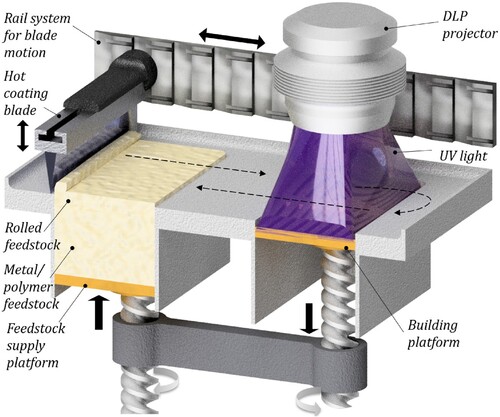
Figure 2. Photosensitive metal/polymer feedstock for the lithography metal additive manufacturing process.
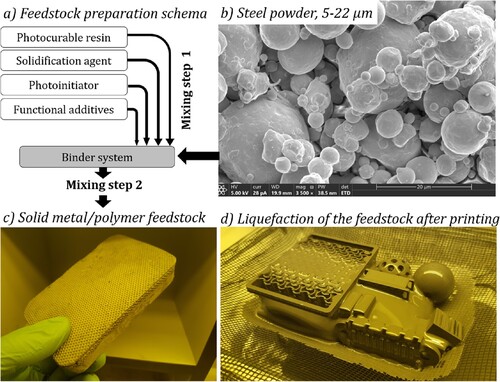
Figure 3. Mechanical testing setup with digital image correlation.
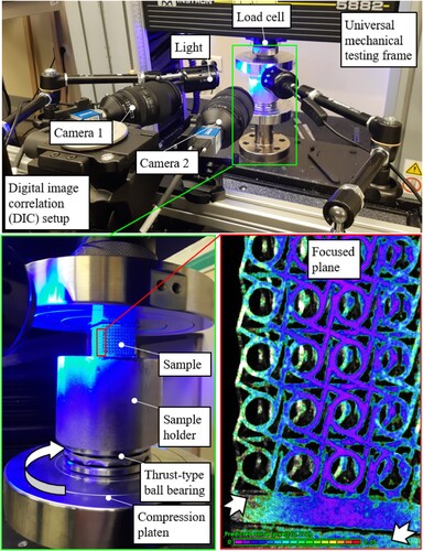
Figure 4. Effect of overpolymerisation on geometrical accuracy in microstructures.
Figure 5. Effect of energy dose on overpolymerisation in lithography metal manufacturing.
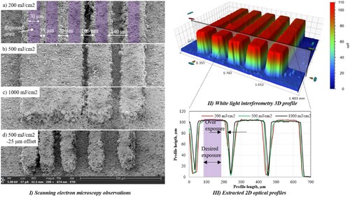
Figure 6. Printing resolution and minimum feature size using lithography metal additive manufacturing.
Figure 7. Lithographic metal additive manufacturing of the overhanding microstructures: spanning helix inspired by metamaterials in Ref. [Citation8].
![Figure 7. Lithographic metal additive manufacturing of the overhanding microstructures: spanning helix inspired by metamaterials in Ref. [Citation8].](/cms/asset/95740414-d86e-42a2-b5a1-e95c73f39628/nvpp_a_2339368_f0007_ob.jpg)
Figure 8. Simulated (with permission from Ref. [Citation39]) and printed metallic twist metamaterials using lithography metal additive manufacturing (this study).
![Figure 8. Simulated (with permission from Ref. [Citation39]) and printed metallic twist metamaterials using lithography metal additive manufacturing (this study).](/cms/asset/64ef99e6-9777-47c0-aac1-accd7ff5ced0/nvpp_a_2339368_f0008_oc.jpg)
Figure 9. The effect of microstructures size on the decaking of metamaterials printed via lithography metal additive manufacturing.
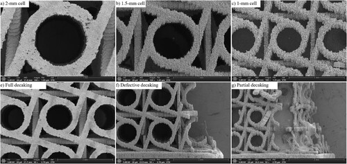
Figure 10. Insufficient strength of green microstructures when scaling up the part size in lithography metal additive manufacturing (exemplified for twist metamaterials and microsprings).
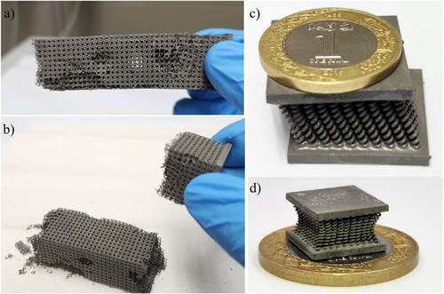
Figure 11. Support frame as a solution for the insufficient strength of green microstructures when scaling up the part size in lithography metal additive manufacturing (exemplified for auxetic and twist metamaterials).
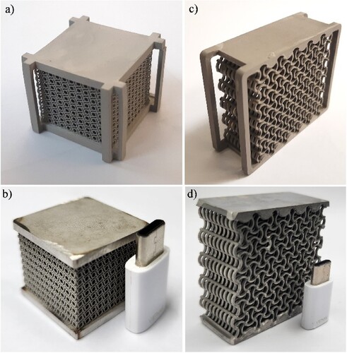
Figure 12. Effect of the 3D printing orientation on the strength of green parts in lithographic metal additive manufacturing (example of comb drives MEMS).
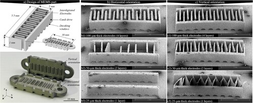
Figure 13. The effect of temperature on surface composition during the debinding process. (d – f) Colours are graded digitally to contrast the metallic powder (blue) from the organic binder (yellow).
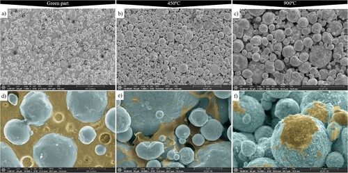
Figure 14. Effect of sintering temperature on the shape stability of auxetic metamaterials (40 × 40 × 20 mm each sample).
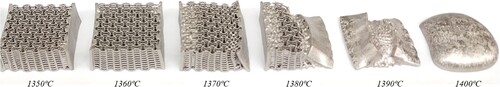
Figure 15. Effect of sintering temperature on strength of auxetic metamaterials.
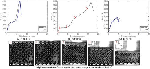
Figure 16. Compressive response of twist metamaterials.
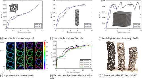
Figure 17. Comparing the print accuracy of (a) selective laser melting to (b) lithography metal additive manufacturing and (c) surface roughness of binder jetting to (d) lithography metal additive manufacturing.
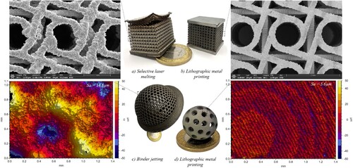
Figure 18. Map of productivity vs accuracy of additive manufacturing technologies (reproduced with permission from Ref. [Citation22]). 2PP: two-photon lithography, EBID: electron beam-induced deposition, SLS: selective laser sintering, EHDP: electrohydrodynamic printing, DIW: direct ink writing, FFF: fused filament fabrication, IJ: inkjet printing, (Pμ)SL: projection microstereolithography, CLIP: continuous liquid interphase printing, CAL: computed axial lithography, LMAM: lithography metal additive manufacturing.
![Figure 18. Map of productivity vs accuracy of additive manufacturing technologies (reproduced with permission from Ref. [Citation22]). 2PP: two-photon lithography, EBID: electron beam-induced deposition, SLS: selective laser sintering, EHDP: electrohydrodynamic printing, DIW: direct ink writing, FFF: fused filament fabrication, IJ: inkjet printing, (Pμ)SL: projection microstereolithography, CLIP: continuous liquid interphase printing, CAL: computed axial lithography, LMAM: lithography metal additive manufacturing.](/cms/asset/06abc548-60d8-4685-b8d0-e2c58193fcf3/nvpp_a_2339368_f0018_oc.jpg)
Table 1. Comparison of widely used metal additive manufacturing technologies with lithography metal additive manufacturing.
Supplemental Material
Download MS Word (7.1 MB)Data availability statement
The authors confirm that the data supporting the findings of this study are available within the article and its supplementary materials. Raw DIC data were generated within the MCEM lab at KAUST. Derived data supporting the findings of this study are available from the corresponding authors on request.