
Figures & data
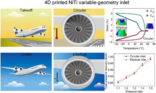
Figure 1. Application of 4D printing technology in the design of variable-geometry inlets for aero engines. (a)-(f) Civil aircraft at takeoff and cruise and the corresponding inlet shapes and the corresponding crystal structures of NiTi alloys. (a) Aircraft during the takeoff phase; (b) Circular design of the inlet during takeoff to accommodate low-speed, high-volume air intake with a working temperature of approximately 60°C; (c) State of the NiTi shape memory alloy material in the inlet duct during takeoff, in the austenite phase; (d) Aircraft during high-altitude cruising; (e) Elliptical design of the inlet during cruising to optimise aerodynamic performance in high-speed airflow with an ambient temperature of approximately −40°C; (f) State of the NiTi shape memory alloy material in the inlet duct during high-altitude cruising, in the R-phase state. (g)-(i) 4D printed inlet and finite element analysis (FEA) of the printing process. (g) 4D printed NiTi inlet after lathe milling process. (h) Residual stresses distribution of the as-printed inlet and 3 observation points marked as point A, point B and Point C in the 5th, 25th and 45th layer, respectively. (i) Thermal history of the three points. (J) Von Mises stress evolution of the three points.
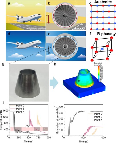
Figure 2. Microstructural features and phase transformation behaviour of the 4D printed variable-geometry inlet. (a) Inverse pole figure map and kernel average misorientation map of the as-printed inlet. (b) {100}B2 pole figure of the area shown in (a). (c) 2D model of the inlet shows the 15° angle between generatrix of the conical tube and the building direction. (d) BF-STEM image and corresponding selective area diffraction pattern of the direct ageing sample. (e) Schematic diagram of the directionally distributed Ni4Ti3 under residual stresses. (f-h) BF-STEM images present the microstructure evolution of the 4D printed variable-geometry inlet. (i-k) Phase transformation behaviour evolution of the 4D printed variable-geometry inlet.
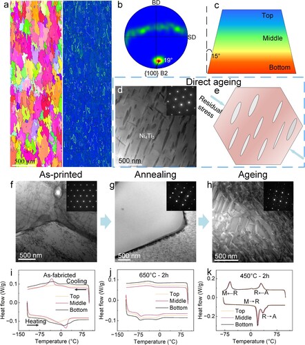
Figure 3. DSC and DMA results illustrating the phase transformation temperature stability and two-way shape memory performance stability of the LDED-formed NiTi alloy after post-treatment, as well as HRTEM characterisation of the B2 and R-phase. (a) DSC curves for 20 cycles from −40°C to 60°C, showing excellent phase transformation temperature stability; (b) DMA strain-temperature curves for 10 cycles from −40°C to 65°C, demonstrating high reproducibility and good stability of the two-way shape memory effect. (c) BF-STEM image of the sample after annealing and stress-assisted aging heat treatment; (d) Selected area electron diffraction (SAED) pattern of the region in (c), showing the orientation relationship of [0 −1 1]B2//[0 −1 0]R; (e) Simulated SAED pattern of B2 and R-phase, indicating the presence of twins in the R-phase, with the twinning plane being {111}R; (f) HRTEM image of the same sample as in (c); (f1) FFT image of the red rectangular area in (f), indicating a single B2 phase; (f2) FFT image of the blue rectangular area in (f), showing a B2-R two-phase region; (f3) IFFT image of the (f1) region; (f4) IFFT image of the (f2) region, demonstrating the coherent interface between B2 and R-phase.
![Figure 3. DSC and DMA results illustrating the phase transformation temperature stability and two-way shape memory performance stability of the LDED-formed NiTi alloy after post-treatment, as well as HRTEM characterisation of the B2 and R-phase. (a) DSC curves for 20 cycles from −40°C to 60°C, showing excellent phase transformation temperature stability; (b) DMA strain-temperature curves for 10 cycles from −40°C to 65°C, demonstrating high reproducibility and good stability of the two-way shape memory effect. (c) BF-STEM image of the sample after annealing and stress-assisted aging heat treatment; (d) Selected area electron diffraction (SAED) pattern of the region in (c), showing the orientation relationship of [0 −1 1]B2//[0 −1 0]R; (e) Simulated SAED pattern of B2 and R-phase, indicating the presence of twins in the R-phase, with the twinning plane being {111}R; (f) HRTEM image of the same sample as in (c); (f1) FFT image of the red rectangular area in (f), indicating a single B2 phase; (f2) FFT image of the blue rectangular area in (f), showing a B2-R two-phase region; (f3) IFFT image of the (f1) region; (f4) IFFT image of the (f2) region, demonstrating the coherent interface between B2 and R-phase.](/cms/asset/e5ae38cf-33d1-4ee6-90cf-5e24436a366e/nvpp_a_2382166_f0003_oc.jpg)
Figure 4. Adaptive deformation capability of the 4D printed variable-geometry inlet. Displacement fields of the inlet with respect to the (a) U, (b) V and (c) W directions. The inlet was first heated up to 60°C and held for 5 min to stabilise the shape, and then cooled down to −40°C to have martensitic transformation. The inlet was then reheated to 60°C, where a martensitic reverse transformation occurs to revert to the high-temperature shape. (d) Strain (ϵyy, ϵxy, ϵxx) – time and (e) temperature curves.
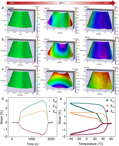
Figure 5. Computational fluid dynamics simulation results of the 4D printed variable-geometry inlet. Total pressure distribution maps for the (a) circular and (b) elliptical inlets at outlet static pressure ratios of 1.1, 1.3, and 1.5 as typical examples; (c) Total pressure recovery factor as a function of outlet static pressure ratio.
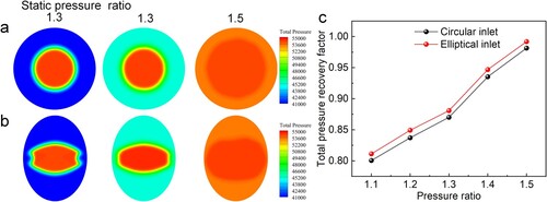
Table 1. The performance of 4D printed variable-geometry inlet at different outlet static pressure ratio (SPR).
Supplemental Material
Download MS Word (5.1 MB)Data availability statement
The data that support the findings of this study are available from the corresponding author, [Ruidi Li], upon reasonable request.