1,950
Views
54
CrossRef citations to date
0
Altmetric
Original papers

Limited range of motion of hip resurfacing arthroplasty due to unfavorable ratio of prosthetic head size and femoral neck diameter

, , , , &
Pages 748-754 | Received 16 Mar 2007, Accepted 29 Sep 2007, Published online: 08 Jul 2009

Figures & data

Figure 1. Design features of the hip resurfacing implants analyzed.

Figure 1. Design features of the hip resurfacing implants analyzed.

Table 1.  Variations in hip resurfacing design features, pre- and postoperative head-neck ratio, and postoperative femoral offset

Figure 2. Anterolateral view of the CAD model of a 48-mm hip resurfacing reduced by 5%. The femoral offset implant with 165° head coverage in situ, with a cup position of 45° inclina-rose with the patient's femoral tion and 15° anteversion. Left: starting position for flexion movement with a head size. The diagrams in Figure straight leg. Right: end position with an anterior impingement of femoral neck at the acetabular component (flexion angle: 77°).

Figure 2. Anterolateral view of the CAD model of a 48-mm hip resurfacing reduced by 5%. The femoral offset implant with 165° head coverage in situ, with a cup position of 45° inclina-rose with the patient's femoral tion and 15° anteversion. Left: starting position for flexion movement with a head size. The diagrams in Figure straight leg. Right: end position with an anterior impingement of femoral neck at the acetabular component (flexion angle: 77°).

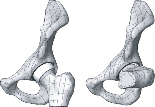
Table 2.  Implant positions analyzed

Figure 3. Overview of range of motion of all implant designs analyzed in 45° inclination and 15° anteversion of the cup. Left: maximum flexion. Middle: maximum internal rotation at 90° flexion, starting from 40° external rotation. Right: maximum external rotation in 15° adduction and 10° extension (b.i.: bony impingement). The dashed line marks physiological ROM (Genoud et al. Citation2000, Tannast et al. Citation2007).

Figure 3. Overview of range of motion of all implant designs analyzed in 45° inclination and 15° anteversion of the cup. Left: maximum flexion. Middle: maximum internal rotation at 90° flexion, starting from 40° external rotation. Right: maximum external rotation in 15° adduction and 10° extension (b.i.: bony impingement). The dashed line marks physiological ROM (Genoud et al. Citation2000, Tannast et al. Citation2007).

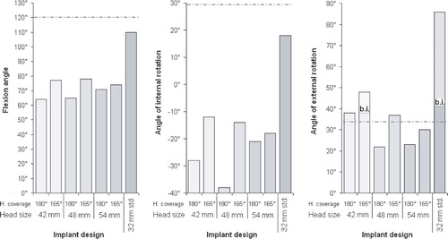
Table 3.  Maximum flexion angles of all implant designs analyzed in all implant positions simulated

Table 4.  Maximum ROM for internal rotation at 90° flexion of all implant designs analyzed in all implant positions simulated

Table 5.  Maximum ROM for external rotation at 15° adduction and 10° extension for all implant designs analyzed in all implant positions simulated. Where bony impingement occurred before prosthetic impingement, the theoretical values for prosthetic impingement are shown in parentheses

Reprints and Corporate Permissions

Please note: Selecting permissions does not provide access to the full text of the article, please see our help page How do I view content?

To request a reprint or corporate permissions for this article, please click on the relevant link below:

Academic Permissions

Please note: Selecting permissions does not provide access to the full text of the article, please see our help page How do I view content?

Obtain permissions instantly via Rightslink by clicking on the button below:

If you are unable to obtain permissions via Rightslink, please complete and submit this Permissions form. For more information, please visit our Permissions help page.